Electronic key device
一种电子钥匙、便携设备的技术,应用在运输和包装、仪器、防窃用的车辆配件等方向,能够解决门或行李箱解锁等问题,达到可靠解锁的效果
- Summary
- Abstract
- Description
- Claims
- Application Information
AI Technical Summary
Problems solved by technology
Method used
Image
Examples
no. 1 Embodiment approach
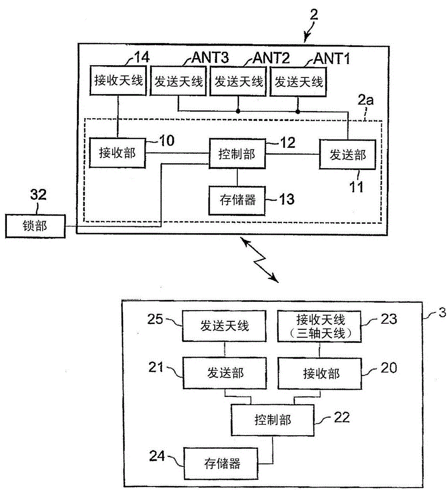
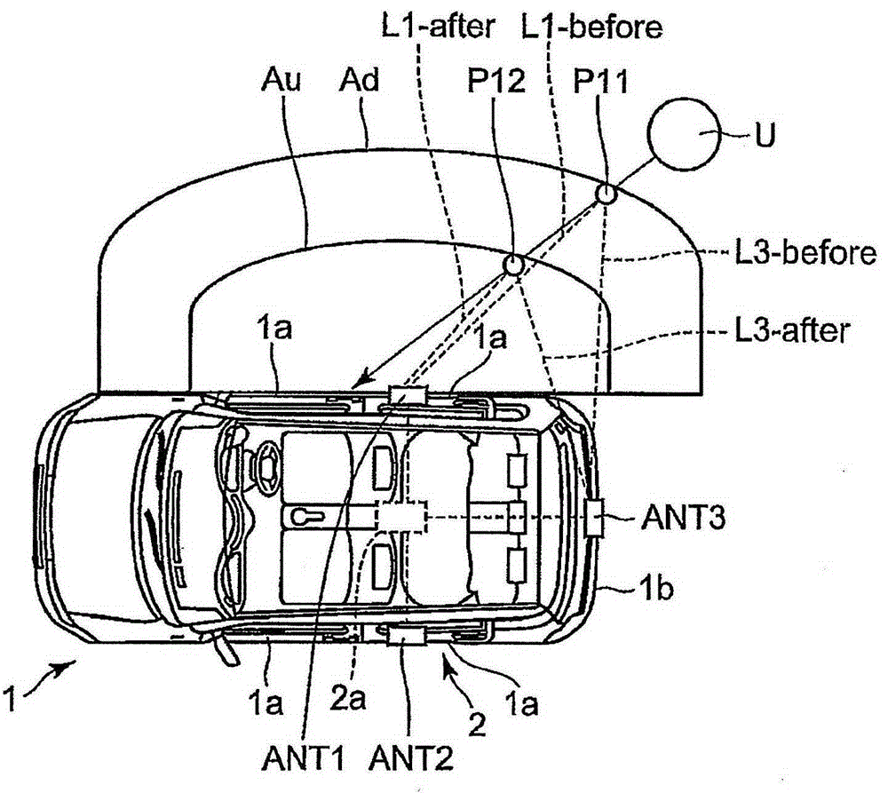
[0051] figure 1 It is a block diagram showing the configuration of the electronic key device according to the first embodiment. also, image 3 The structure of the in-vehicle device in the first embodiment is shown.
[0052] The electronic key device according to the first embodiment is provided with an in-vehicle device 2 on the vehicle 1 side, and performs wireless communication with a portable device 3 carried by the user to unlock a plurality of compartment doors 1a and trunk doors 1b. and other prescribed controls of the vehicle 1 . Here, the doors include a compartment door 1a and a trunk door 1b.
[0053] The in-vehicle device 2 includes an electronic control unit 2 a arranged in the vehicle 1 , three transmitting antennas ANT1 to ANT3 , and a receiving antenna 14 . The electronic control unit 2 a includes a vehicle receiving unit 10 (receiving unit), a vehicle transmitting unit 11 (transmitting unit), a vehicle controlling unit 12 (control unit), and a memory 13 . ...
example 1
[0084] exist image 3 In the example 1 shown, the user U carrying the mobile device 3 is at the position P11 at a certain time, and moves to the position P12 at a time one cycle later. The position P11 is within the proximity detection area Ad, and the position P12 is within the proximity unlocking area Au. By moving from the position P11 to the position P12, the mobile device 3 approaches the vehicle 1 . Here, the distance from each position to each antenna is defined as follows. This definition is also the same for Examples 2-4.
[0085] Distance from position P11 to antenna ANT1: L1-before,
[0086] Distance from position P11 to antenna ANT3: L3-before,
[0087] Distance from position P12 to antenna ANT1: L1-after,
[0088] Distance from position P12 to antenna ANT3: L3-after,
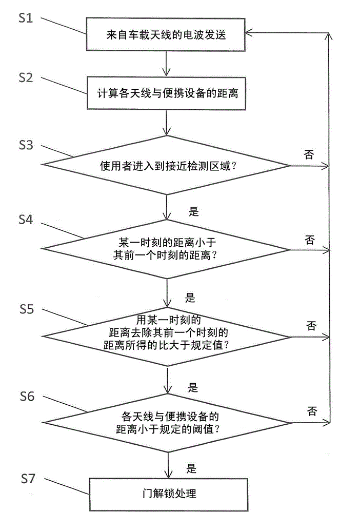
[0089] The processing flow in the electronic key device at this time is as follows.
[0090] (1) The portable device 3 calculates the distance between each antenna and the portable device 3 ba...
example 2
[0097] exist Figure 4 In the example 2 shown, the user U carrying the mobile device 3 is at the position P21 at a certain time, and moves to the position P22 at the time one cycle later. The position P21 is in the approach detection area Ad, and the position P22 is in the approach unlocking area Au, but the movement from the position P21 to the position P22 is a movement parallel to the right compartment door 1a. Here, since the definitions of the distances from the positions P21 and P22 to the respective antennas are the same as those in Example 1, they are omitted.
[0098] The processing flow in the electronic key device at this time is as follows.
[0099] (1) The portable device 3 calculates the distance between each antenna and the portable device 3 based on radio waves received from the in-vehicle device 2 at predetermined intervals. When the user arrives at the position P21, it is judged that the portable device 3 has entered the approach detection area Ad ( figur...
PUM
 Abstract
Description
Claims
Application Information
 - R&D
- Intellectual Property
- Life Sciences
- Materials
- Tech Scout
- Unparalleled Data Quality
- Higher Quality Content
- 60% Fewer Hallucinations
Browse by: Latest US Patents, China's latest patents, Technical Efficacy Thesaurus, Application Domain, Technology Topic, Popular Technical Reports.
© 2025 PatSnap. All rights reserved.Legal|Privacy policy|Modern Slavery Act Transparency Statement|Sitemap|About US| Contact US: help@patsnap.com


