Motor rotor automatic snap spring and bearing pressing machine

A motor rotor and pressure bearing technology is applied in the field of motor assembly and processing equipment, which can solve the problems of unstable products, low assembly efficiency, and large labor input, so as to improve the yield and process accuracy, reduce labor costs, and improve the degree of automation. Effect

Active Publication Date: 2016-01-13
GREE ELECTRIC APPLIANCES INC +2
View PDF8 Cites 8 Cited by
  • Summary
  • Abstract
  • Description
  • Claims
  • Application Information

AI Technical Summary

Problems solved by technology

[0005] The purpose of the present invention is to propose a motor rotor automatic clamp spring pressure bearing machine, which can solve the problems of low assembly efficiency, large manual investment and unstable products in the process of clamp spring pressure bearing existing in the prior art

Method used


Image

  • Motor rotor automatic snap spring and bearing pressing machine
  • Motor rotor automatic snap spring and bearing pressing machine
  • Motor rotor automatic snap spring and bearing pressing machine

Examples


Embodiment Construction

[0028] The technical solutions of the present invention are further described below with reference to the accompanying drawings and through specific embodiments.

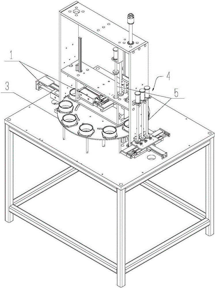
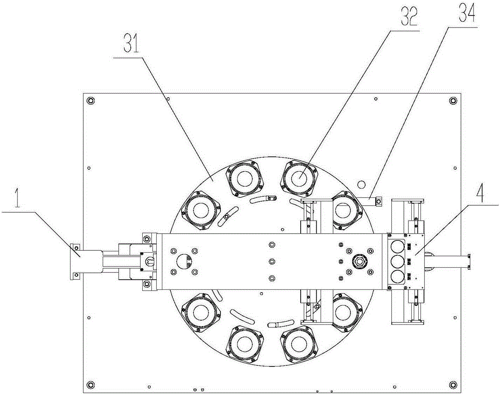
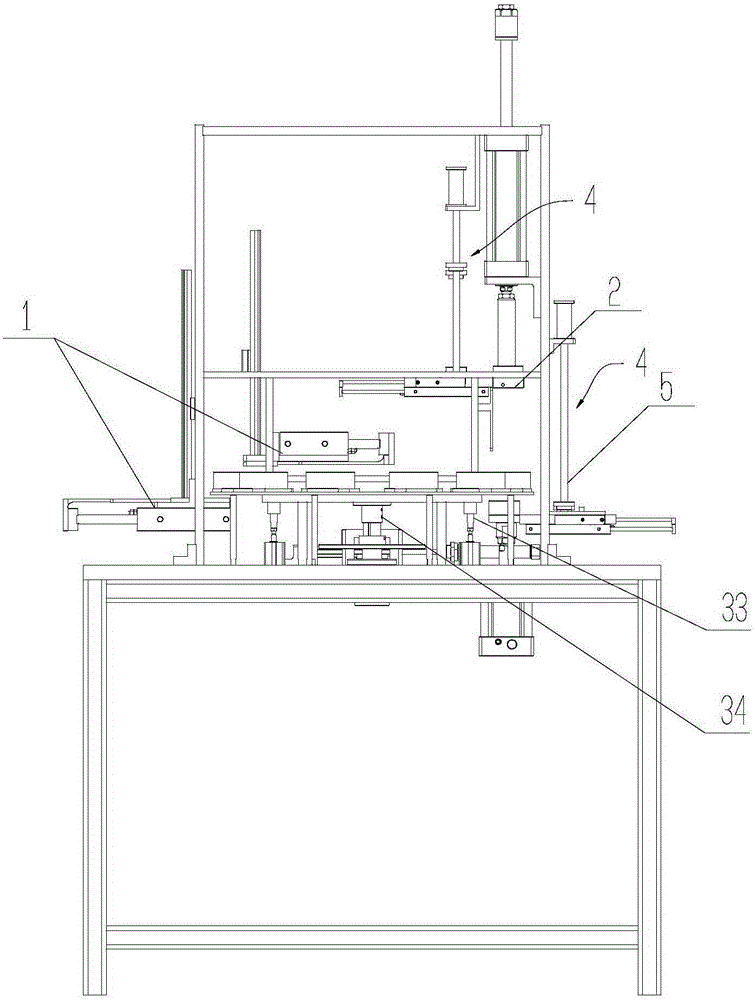
[0029] like Figure 1 to Figure 3 As shown, this embodiment provides a motor rotor automatic circlip press bearing machine, including a circlip press-in device 1, a bearing press-in device 2, a motor rotor conveying device 3, a rotor position detection device and a control device, the control device The operating states of the circlip press-fitting device 1 , the bearing press-fitting device 2 and the motor rotor conveying device 3 are controlled according to the rotor position detected by the rotor position detection device.

[0030] In this embodiment, through the mutual cooperation between the sensor, the control device, the circlip pressing device 1, the bearing pressing device 2, and the motor rotor conveying device 3, the process of punching the circlip and pressing the bearing of the rotor can be realized aut...


PUM


Abstract

The invention relates to a motor assembling processing device field, and particularly relates to a motor rotor automatic snap spring and bearing pressing machine. The motor rotor automatic snap spring and bearing pressing in machine comprises a snap spring pressing in device, a bearing pressing in device, a motor rotor carrying device, a rotor position detection device and a control device; and the control device controls the working conditions of the snap spring pressing in device, the bearing pressing in device and the motor rotor carrying device according to the rotor position detected by the rotor position detection device. The motor rotor automatic snap spring and bearing pressing machine can realize automatic snap spring pressing of the rotor and bearing pressing technology through the mutual operation between a sensor, a control device, a snap spring pressing in device, a bearing pressing in device, and the motor rotor carrying device, which improves the automation level of the motor rotor assembling, reduces the labor cost, improves the rate of the good product of the rotor processing and the technology precision.

Description

technical field [0001] The invention relates to the field of motor assembly and processing equipment, in particular to a motor rotor automatic compression spring-pressed bearing machine. Background technique [0002] At present, the traditional motor rotor pressing circlip operation relies on manually holding the motor rotor to press the circlips at both ends, and then placing the bearing (short shaft end bearing) in the tooling under the pressure bearing, and putting the bearing on the other end of the motor rotor (long shaft end bearing) , and then place the motor rotor in the tooling under the pressure bearing, put the tooling on the pressure bearing on the long shaft end of the motor rotor, and push it together under the hand-arranging press for crimping work. [0003] In this way, the pressing of the circlip and the bearing is completed by one person, and all the actions must be completed one by one. The single process takes a long time and the assembly efficiency is lo...

Claims


Application Information

Patent Timeline
Patent Type & Authority Applications(China)
IPC IPC(8): H02K15/00H02K15/14B23P21/00
Inventor 赵金强董军华石南
Owner GREE ELECTRIC APPLIANCES INC
Why Eureka
Try Eureka