Flow forwarding method and flow forwarding device for switching system

A switching system and traffic forwarding technology, applied in the field of communication, can solve the problems of high expansion cost and limited expansion capacity of the switching system

Active Publication Date: 2016-01-13
HUAWEI TECH CO LTD
View PDF4 Cites 4 Cited by
  • Summary
  • Abstract
  • Description
  • Claims
  • Application Information

AI Technical Summary

Problems solved by technology

[0005] Embodiments of the present invention provide a traffic forwarding method and device for a switching system to solve the technical problems of limited expansion capacity and high expansion cost of the switching system in the prior art

Method used


Image

  • Flow forwarding method and flow forwarding device for switching system
  • Flow forwarding method and flow forwarding device for switching system
  • Flow forwarding method and flow forwarding device for switching system

Examples


Embodiment Construction

[0088] In order to make the purpose, technical solutions and advantages of the embodiments of the present invention clearer, the technical solutions in the embodiments of the present invention will be clearly and completely described below in conjunction with the drawings in the embodiments of the present invention. Obviously, the described embodiments It is a part of embodiments of the present invention, but not all embodiments. Based on the embodiments of the present invention, all other embodiments obtained by persons of ordinary skill in the art without creative efforts fall within the protection scope of the present invention.

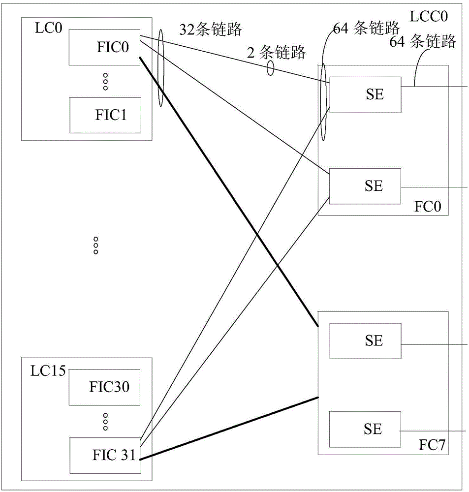
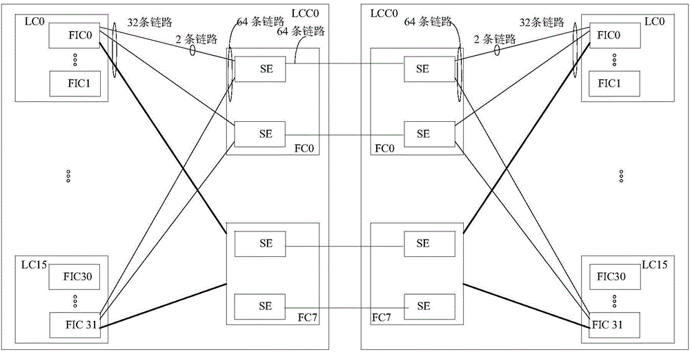
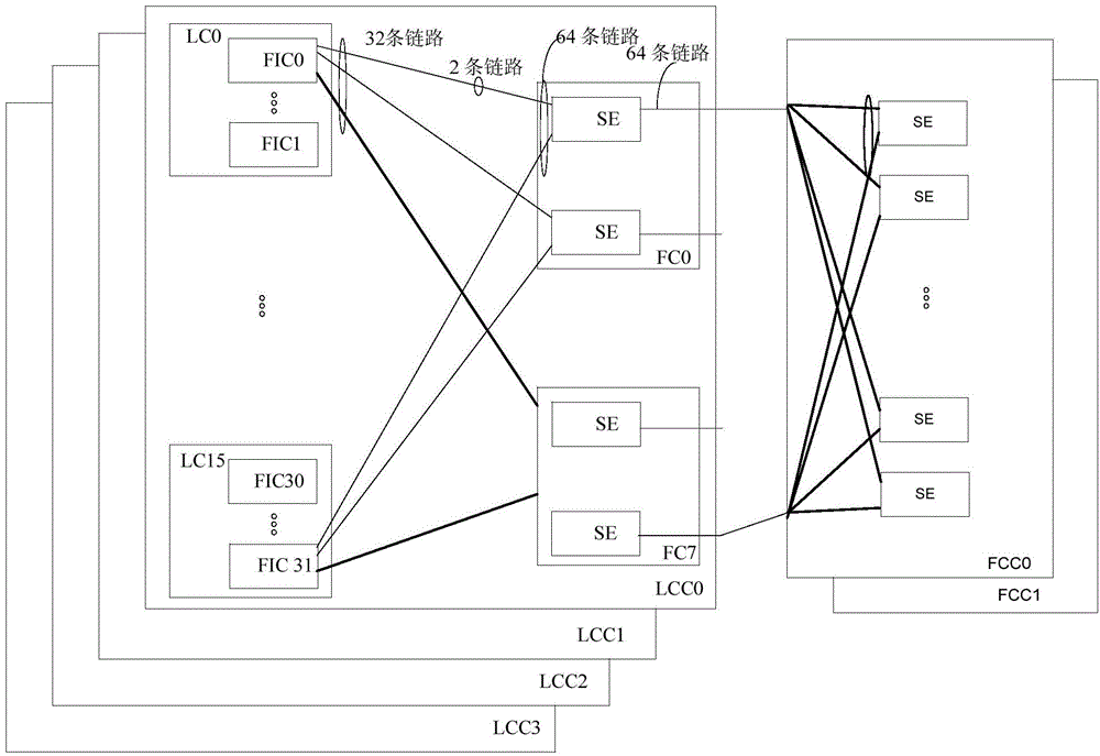
[0089] Figure 4 It is a schematic flowchart of a traffic forwarding method of a switching system provided in Embodiment 1 of the present invention. The method is applied to a switching system, and the switching system includes a first LCC, at least one second LCC and a third LCC interconnected according to a wireless mesh (mesh) topology. Here,...


PUM


Abstract

Embodiments of the invention provide a flow forwarding method and a flow forwarding device for a switching system. The switching system comprises a first LCC, at least one second LCC and a third LCC which are interconnected according to a mesh topology. The method comprises the steps as follows: the first LCC receives a data packet and parses the data packet to acquire the destination address of the data packet; and when the destination address indicates that the data packet is to be sent to the third LCC, the first LCC carries the data packet on a third link and forwards the data packet to the third LCC if the current preset configuration mode of the switching system is a first configuration mode, wherein the first configuration mode indicates that the switching system is currently in an N-jump mode, and N is a natural number greater than or equal to 3. By adopting the method provided by the embodiment of the invention, wire-speed forwarding of a data packet between any two nodes in the switching system is realized, the expansion ability of the switching system is enhanced, and the expansion cost of the switching system is reduced.

Description

technical field [0001] Embodiments of the present invention relate to communication technologies, and in particular to a traffic forwarding method and device for a switching system. Background technique [0002] In a switching system, generally at least one line card (Line Card, hereinafter referred to as LC) and at least one switching fabric board (Fabric Card, hereinafter referred to as FC) constitute a line card chassis (Line Card Chassis, hereinafter referred to as LCC). Wherein, each LC in the LCC includes at least one switching fabric interface chip (Fabric Interface, hereinafter referred to as FIC) chip, and each FC includes at least one switching fabric chip (SwitchElement, hereinafter referred to as SE). Such as figure 1 As shown, there are 16 LCs (LC0 to LC15) and 8 FCs (FC0 to FC7) in the LCC0 line card frame, and there are 32 FICs (FIC0 to FIC31) and 16 SEs ( figure 1 Each FC shown contains two SEs), and the FIC side of each SE chip (that is, the left side of t...

Claims


Application Information

Patent Timeline
Patent Type & Authority Applications(China)
IPC IPC(8): H04L12/741H04L12/937H04L45/74H04L45/28
CPCH04L49/15H04L41/0668H04L45/28H04L45/74H04L47/122
Inventor 林云
Owner HUAWEI TECH CO LTD
Why Eureka
Try Eureka