Control system and method for controlling the orientation of a segment of a manipulator

A technology for adjusting the system and controlling operation, applied in the field of hydraulic actuation components and electro-hydraulic control flow path, it can solve the problems of weakening the performance of the electro-hydraulic control flow path adjustment system and cannot be determined, so as to increase the available space and reduce pipeline breakage opportunities, cost reduction effects

Active Publication Date: 2016-01-13
TTCONTROL
View PDF5 Cites 5 Cited by
  • Summary
  • Abstract
  • Description
  • Claims
  • Application Information

AI Technical Summary

Problems solved by technology

Therefore, vibrations (e.g. due to static friction) acting on a stationary hydraulic cylinder cannot be determined
Furthermore, unaccounted for dynamic effects, which are caused, for example, by a non-ideal pressure supply, can have a direct influence on the measurement signal to be fed back and thus impair the performance of the electrohydraulic control circuit or the associated regulation system

Method used


Image

  • Control system and method for controlling the orientation of a segment of a manipulator
  • Control system and method for controlling the orientation of a segment of a manipulator
  • Control system and method for controlling the orientation of a segment of a manipulator

Examples


Embodiment Construction

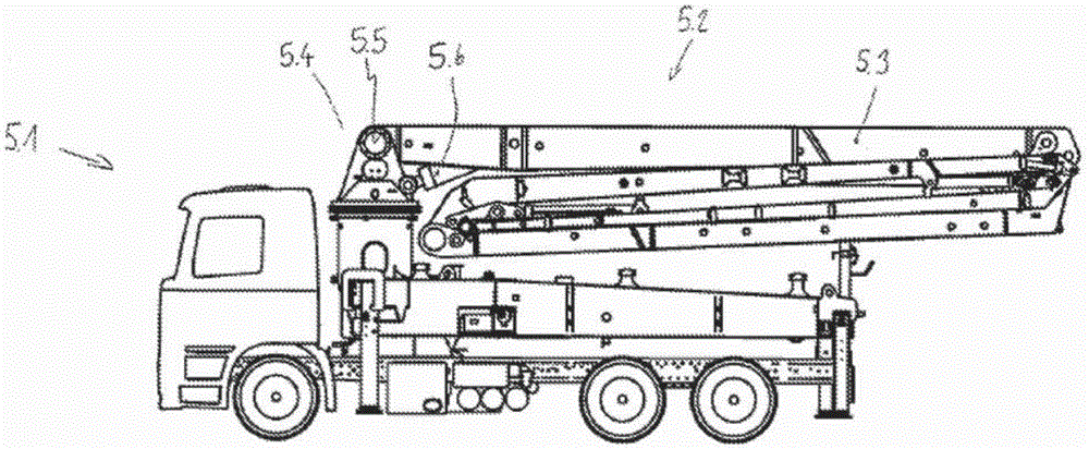
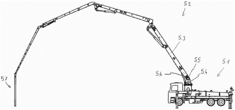
[0052] figure 1 A transport vehicle 5.1 is shown in side view with a large manipulator 5.2, wherein the large manipulator 5.2 has several sections 5.3. figure 1 Several sections 5.3 are shown, where only the first section 5.3 is given a reference number in order to make the diagram easier to read. Subsequent sections 5.3 may be structured substantially the same, but each subsequent section 5.3 is connected to the previous section 5.3. The first section 5.3 is connected by a joint 5.5 to a base 5.4, wherein the embodiment of the base 5.4 is, for example, a rotary gear rotatable about a vertical axis, which is fixed relative to the vehicle. But alternatively, the base 5.4 can be designed in any other way - the important point is that the first section 5.3 is connected to the base 5.4 by a joint 5.5.

[0053] The first actuating element 5.6 is arranged between the base 5.4 and the first section 5.3 and is preferably in the form of a hydraulic cylinder; of course the actuating e...


PUM


Abstract

The invention relates to a control system for controlling the orientation of a segment (5.3) of a manipulator, in particular of a large manipulator for self-propelled concrete pumps, the segment (5.3) being connected to a base (5.4) or a preceding segment (5.3) of the manipulator by means of a joint (5.5) and being pivotable at the joint (5.5) in relation to the base (5.4) or the preceding segment (5.3) about at least one axis of rotation by means of at least one control element (5.6), preferably at least one hydraulic control element, characterised in that the control system comprises at least: - a first sensor (4.1), which is arranged on a segment (5.3) connected to the joint (5.5) and provides a first measurement signal, which corresponds to a deformation of the segment (5.3) and is called a ''deformation signal'', - a second sensor (4.2, 4.3), which provides a second measurement signal, which corresponds to the spatial orientation of the segment (5.3) connected to the joint (5.5) and is called an ''orientation signal'', and - at least one control element (5.6) associated with the joint (5.5); and is designed to process the deformation signal and the orientation signal as input variables and to determine a control signal from the deformation signal and the orientation signal while taking into account a target orientation of the segment (5.3) associated with the joint (5.5), which control signal is fed to the associated control element (5.6).

Description

technical field [0001] The present invention relates to an adjustment system for controlling the orientation of a section of an operator, especially a large operator for a vehicle-mounted concrete delivery pump, wherein the section is articulated to the base of the operator or to the previous section, And can be pivoted relative to the base or the previous joint around at least one rotation axis by at least one actuating element, preferably a hydraulic actuating element. [0002] The invention also relates to an electro-hydraulic control flow circuit for driving a hydraulically actuated actuating element, so that it is possible to adjust a section of an operator, especially a large operator for a vehicle-mounted concrete delivery pump, in its orientation Make adjustments. Background technique [0003] The current electro-hydraulic control flow path or its associated adjustment system (such as the flow path or system used to drive a multi-section large-scale operator for a v...

Claims


Application Information

Patent Timeline
IPC IPC(8): E04G21/04B66C13/06
CPCB66C13/066B66C13/18B66F9/20E04G21/04E04G21/0454E04G21/0436E04G21/0463
Inventor W·特比克W·克门木勒汝J·贺尼克里
Owner TTCONTROL
Why Eureka
Try Eureka