Spherical workpiece clamping mechanism

A clamping mechanism and workpiece technology, applied in the direction of metal processing machinery parts, clamping, manufacturing tools, etc., can solve the problems of small adjustment amount and slow adjustment efficiency, and achieve the effect of fast adjustment, simple structure, and improved adjustment efficiency

Inactive Publication Date: 2016-01-20
张家港市紫东机械科技有限公司
View PDF8 Cites 27 Cited by
  • Summary
  • Abstract
  • Description
  • Claims
  • Application Information

AI Technical Summary

Problems solved by technology

[0002] Spherical workpieces need to be centered and clamped for accurate processing during processing. In the process of adjusting the centering and clamping, the adjustment amount each time is very small, resulting in relatively slow adjustment efficiency.

Method used


Image

  • Spherical workpiece clamping mechanism

Examples


Embodiment Construction

[0013] The technical scheme of the present invention will be described in further detail below in conjunction with the accompanying drawings and specific embodiments, so that those skilled in the art can better understand the present invention and implement it, but the examples given are not intended to limit the present invention.

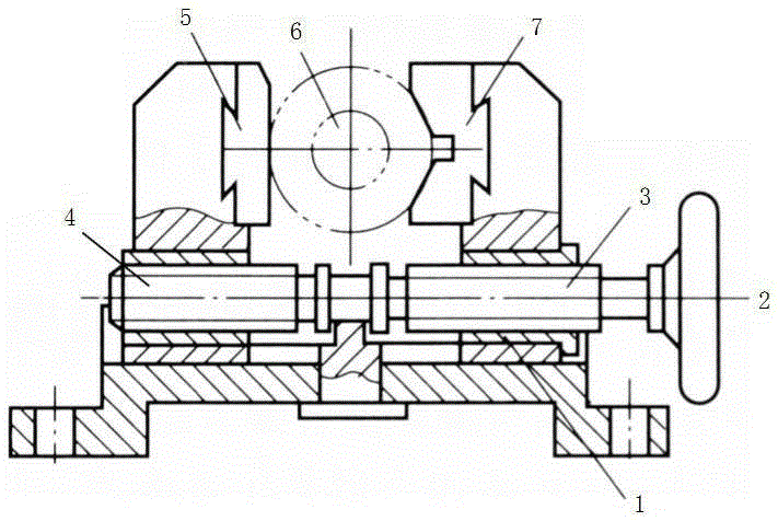
[0014] A spherical workpiece clamping mechanism, comprising a base 1, such as figure 1 As shown, the base 1 is horizontally provided with a lead screw 2, and the two ends of the lead screw 2 are respectively provided with threads in opposite directions, for example, figure 1 The right end of the leading screw 2 is provided with a left-handed thread 3, and the left end is provided with a right-handed thread 4, preferably the threads at both ends of the leading screw 2 are identical and equally spaced. Wherein, the center of the lead screw 2 may not be provided with threads, so that a certain distance is left between the threads at both ends.

[00...


PUM


Abstract

The invention discloses a spherical workpiece clamping mechanism which comprises a base. The spherical workpiece clamping mechanism is characterized in that a lead screw is horizontally arranged on the base, the two ends of the lead screw are provided with threads in the opposite directions respectively, and a plane jaw clamping pawl and a V-shaped clamping pawl used for centering and clamping a spherical workpiece are arranged at the two ends of the lead screw respectively. Preferably, the threads at the two ends of the lead screw are arranged at equal intervals and the inner wall of the V-shaped clamping pawl is provided with a concave face corresponding to the spherical workpiece. By the adoption of the spherical workpiece clamping mechanism, adjustment efficiency is improved and the workpiece can be rapidly adjusted to the accurate position.

Description

technical field [0001] The invention relates to a spherical workpiece clamping mechanism. Background technique [0002] Spherical workpieces need to be centered and clamped for precise processing during processing. In the process of adjusting the centering and clamping, the adjustment amount each time is very small, resulting in relatively slow adjustment efficiency. Contents of the invention [0003] In view of the above problems, the present invention provides a spherical workpiece clamping mechanism, which improves the adjustment efficiency and can quickly adjust to an accurate position. [0004] In order to achieve the above-mentioned technical purpose and achieve the above-mentioned technical effect, the present invention is realized through the following technical solutions: [0005] A spherical workpiece clamping mechanism, comprising a base, characterized in that a lead screw is horizontally arranged on the base, the two ends of the lead screw are respectively pro...

Claims


Application Information

Patent Timeline
Patent Type & Authority Applications(China)
IPC IPC(8): B23Q3/06B25B1/10B25B1/20B25B1/24
CPCB23Q3/066B23Q3/062B25B1/103B25B1/20B25B1/2415
Inventor 缪建祥
Owner 张家港市紫东机械科技有限公司
Why Eureka
Try Eureka