Feeding and splitting system for tool

A material feeding and machine tool technology, applied in the field of numerical control processing, can solve problems such as high labor intensity, inadequate clamping, and low production efficiency, and achieve the effect of reducing labor intensity and improving material feeding efficiency

Inactive Publication Date: 2016-01-20
CHONGQING OUBOTE INTELLIGENT ROBOT TECH CO LTD
View PDF7 Cites 5 Cited by
  • Summary
  • Abstract
  • Description
  • Claims
  • Application Information

AI Technical Summary

Problems solved by technology

[0002] At present, the processing of piston parts relies on manual loading and clamping. After the lathe processing is completed, it is manually disassembled and the processed parts are transported to the designated position for the next clamping. Manual loading and unloading is not only labor-intensive large, low production efficiency, and at the same time, in

Method used


Image

  • Feeding and splitting system for tool
  • Feeding and splitting system for tool
  • Feeding and splitting system for tool

Examples


Embodiment Construction

[0018] The implementation of the present invention will be illustrated by specific specific examples below, and those skilled in the art can easily understand other advantages and effects of the present invention from the contents disclosed in this specification.

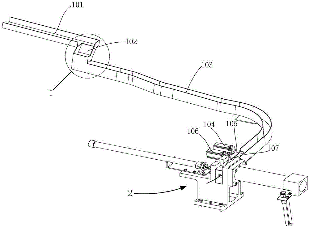
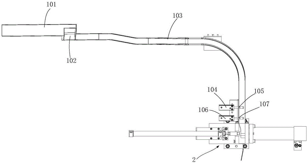
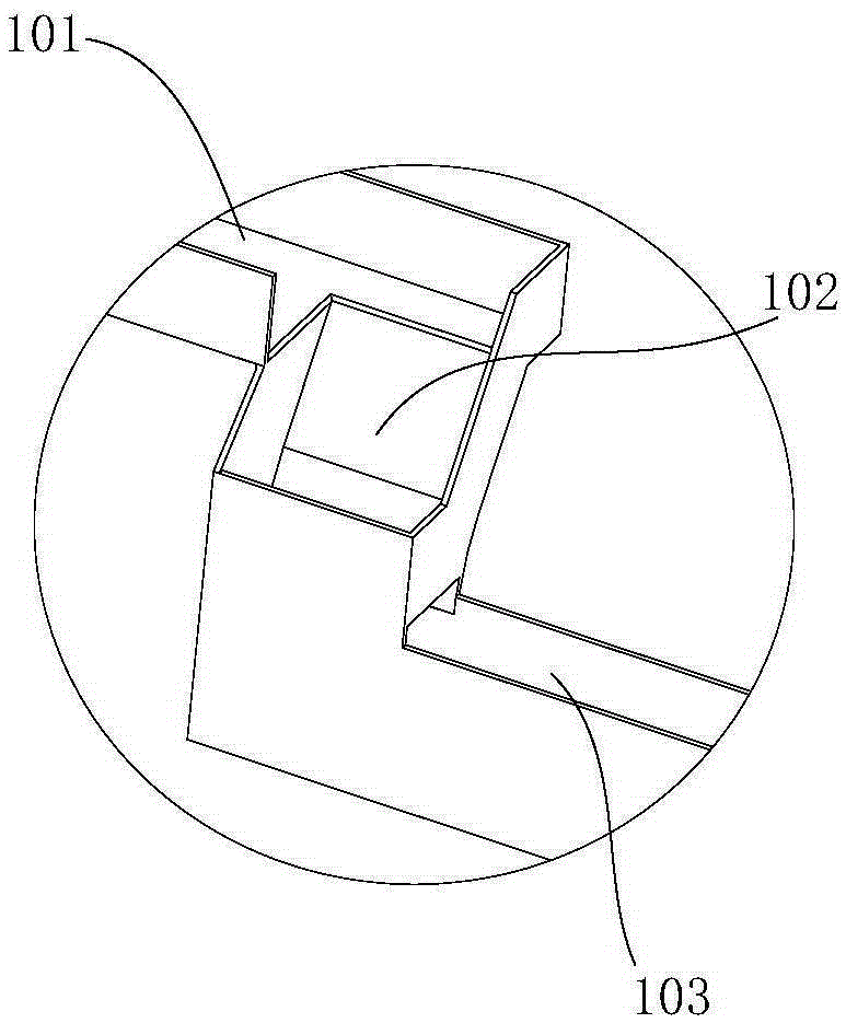
[0019] Such as figure 1 and figure 2 As shown, a feeding and distributing system of a machine tool includes a track groove for carrying workpieces. One end of the track groove is the feeding position, and the other end is the material distribution position. The track groove is used to transfer the workpiece from the previous process to the current process. For the lathe, the track groove can be erected on the lathe or on other auxiliary supporting mechanisms. The track groove needs to form a certain slope so that the workpiece can roll by itself under the action of gravity. The material distribution level is close to the pushing mechanism 2 of the machine tool, and the material distribution level of the track groo...


PUM


Abstract

The invention provides a feeding and splitting system for a tool. The system comprises a track groove which is used for bearing a workpiece; a feeding position is formed at one end of the track groove and a splitting position is formed at the other end of the track groove; two material blocking mechanisms are arranged side by side at the splitting position of the track groove; each material blocking mechanism comprises a splitting air cylinder and a blocking rod connected onto the air cylinder; blocking rods of the two material blocking mechanisms are parallel to each other; sensors are arranged on both two splitting air cylinders; and a conversion device which is used for changing the placing pose of the workpiece is arranged at the position close to the feeding position of the track groove. According to the feeding and splitting system, a workpiece in the former process can be fed to the next process automatically and conveniently; and at the same time, poses can be converted automatically, and only one workpiece is guaranteed to be fed every time through a two-stage splitting mechanism.

Description

technical field [0001] The invention belongs to the technical field of numerical control processing, and in particular relates to a feeding and distributing system of a machine tool. Background technique [0002] At present, the processing of piston parts relies on manual loading and clamping. After the lathe processing is completed, it is manually disassembled and the processed parts are transported to the designated position for the next clamping. Manual loading and unloading is not only labor intensive. Large, low production efficiency, and in the process of clamping, it is easy to have insufficient clamping and inconvenient clamping and positioning, resulting in unqualified processed products. Therefore, it is difficult for the product to meet the design requirements. At the same time, the traditional clamping production method is adopted, which requires more operators and higher labor costs. Therefore those skilled in the art urgently need a kind of numerically contro...

Claims


Application Information

Patent Timeline
IPC IPC(8): B23Q7/12B23Q7/16
CPCB23Q7/12B23Q7/16
Inventor 汪传宏
Owner CHONGQING OUBOTE INTELLIGENT ROBOT TECH CO LTD
Why Eureka
Try Eureka