Wind turbine pitch angle control method, device and system
A technology for a wind turbine and a control method, which is applied in the control of wind turbines, wind turbines, and wind power generation, etc., to achieve the effects of eliminating blade stall, improving power generation efficiency, and improving power curves.
- Summary
- Abstract
- Description
- Claims
- Application Information
AI Technical Summary
Problems solved by technology
Method used
Image
Examples
Embodiment 1
[0032] image 3 It is a flow chart of the control method for the pitch angle of the wind power generating set in Embodiment 1 of the present invention, such as image 3 As shown, it includes the following steps:
[0033] Step 310: Obtain the output power of the wind turbine in the transition period before full power;
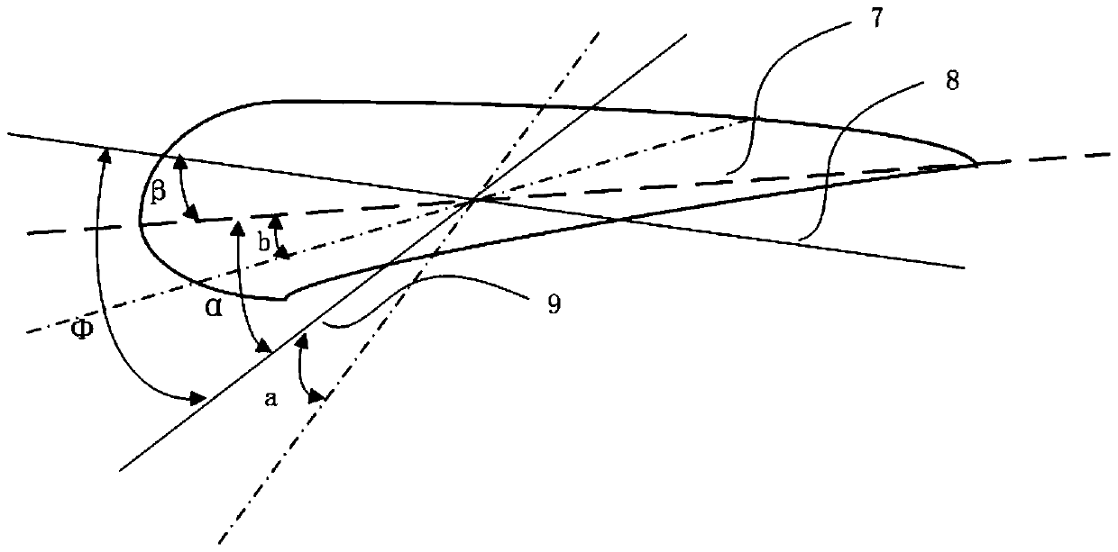
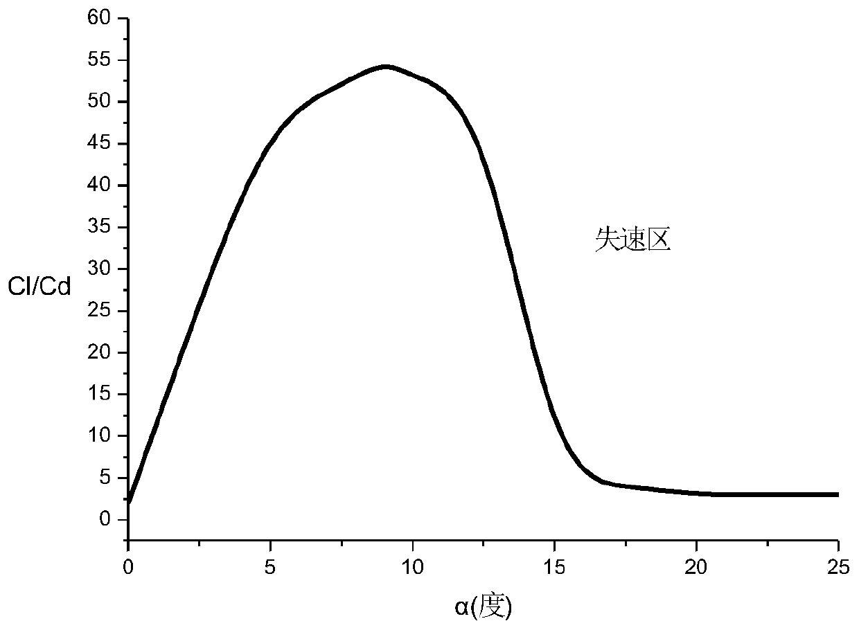
[0034] Step 320: When the output power is abnormal, determine the pitch angle of the blade according to the pre-obtained maximum reference value of the wind direction angle when the blade stalls abnormally, the maximum reference value of the wind direction angle when the blade stalls normally, and the initial minimum pitch angle.
[0035] Among them, there are many ways to judge whether the output power is abnormal, for example, by comparing with the preset standard power threshold, or by comparing the output power curve of the transition section with the preset output power curve, or according to the output The relationship between power and wind speed is jud...
Embodiment 2
[0039] Figure 4 It is a flow chart of obtaining the maximum reference value of the wind direction angle in the second embodiment of the present invention. Such as Figure 4 As shown, it includes the following steps:
[0040] Step 410: collecting a plurality of wind angle values and wind speed information within the first time period;
[0041] Step 420: Generate a wind speed-wind direction standard deviation scatter diagram according to the values of multiple wind direction angles and the wind speed information;
[0042]Step 430: In the wind speed-wind direction standard deviation scatter diagram, generate a reference straight line perpendicular to the wind direction standard deviation axis, so that the data points within the preset range are located below the reference straight line, and according to the wind direction corresponding to the reference straight line The standard deviation value determines the maximum reference value of wind direction angle.
[0043] The ...
Embodiment 3
[0048] This example is for image 3 In step 320, a further detailed description is carried out. During specific implementation, the following methods can be adopted:
[0049] The sum of the maximum reference value of the wind direction angle when the blade stalls abnormally, the maximum reference value of the wind direction angle when the blade stalls normally, and the initial minimum pitch angle is rounded to determine the pitch angle of the blade; or,
[0050] The maximum reference value of the wind direction angle when the blade stalls abnormally, the maximum reference value of the wind direction angle when the blade stalls normally, and the initial minimum pitch angle are rounded and summed with the third value to determine The pitch angle of the blade.
[0051] Specifically, the above-mentioned rounding processing may include: rounding and rounding processing, upward rounding processing, or downward rounding processing.
[0052] Preferably, the pitch angle of the blade ...
PUM
 Abstract
Description
Claims
Application Information
 - R&D
- Intellectual Property
- Life Sciences
- Materials
- Tech Scout
- Unparalleled Data Quality
- Higher Quality Content
- 60% Fewer Hallucinations
Browse by: Latest US Patents, China's latest patents, Technical Efficacy Thesaurus, Application Domain, Technology Topic, Popular Technical Reports.
© 2025 PatSnap. All rights reserved.Legal|Privacy policy|Modern Slavery Act Transparency Statement|Sitemap|About US| Contact US: help@patsnap.com


