PE cable and cable clamp ball connecting performance test method

A test method and connection performance technology, applied in the testing of mechanical parts, the testing of machine/structural parts, and the use of stable tension/pressure to test the strength of materials, etc. , sudden change in stress state, tearing of PE sheath, etc., to achieve the effect of intuitive test results, simple test device and reliable test data

Active Publication Date: 2016-01-20
ZHEJIANG JINGGONG STEEL BUILDING GRP +1
View PDF6 Cites 8 Cited by
  • Summary
  • Abstract
  • Description
  • Claims
  • Application Information

AI Technical Summary

Problems solved by technology

[0002] In the large-span cable-strut-beam prestressed space structure, the PE cables are often arranged in the form of one-way long-length arrangement, and the upper rigid structure and the cables are connected in the form of cable clip balls. There is a certain angle, and the axial force of the rigid strut will generate a large unbalanced internal force at the cable clamping ball. These unbalanced internal forces need the friction force between the cable clamping ball and the cable body to resist. When the cable clamping ball’s anti-slip Insufficient force will cause the cable clamp ball to slide along the length of the cable, which will affect the configuration of the cable system, and the stress state of the cable-rod system and the cable force will change suddenly. The PE sheath on the surface of the cable is torn, which affects the anti-corrosion of the cable body and the overall mechanical performance of the structure. Therefore, determining the anti-slip friction coefficient between the cable clamp ball and the cable body and then designing a reasonable cable clamp ball node form is the whole The key to the structural system

Method used


Image

  • PE cable and cable clamp ball connecting performance test method
  • PE cable and cable clamp ball connecting performance test method
  • PE cable and cable clamp ball connecting performance test method

Examples


Embodiment Construction

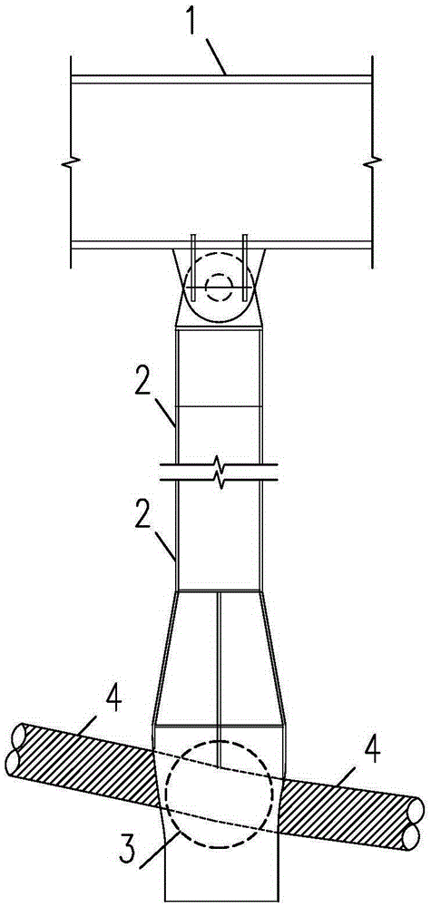
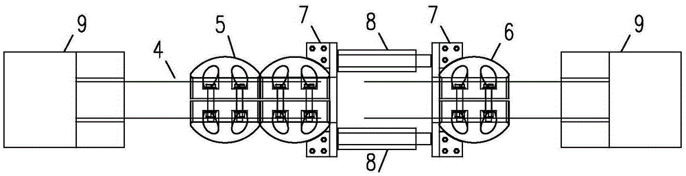
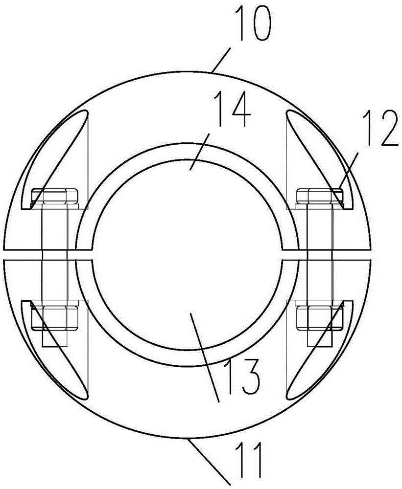
[0023] combined with Figure 1-5 , to further describe the embodiments of the present invention in detail.

[0024] The specification of the PE cable 4 used in this example is Φ7X397, the diameter of the cable body is 183mm, the diameter of the steel wire bundle is 153mm, the thickness of the PE sheath is 15mm, and the breaking load is 25515KN; the tensile force of the PE cable test is 0KN and 2551KN respectively , 5102KN, 7653KN, 10204KN, 12755KN; the specification of tension testing machine 9 is 2000T.

[0025] The material of the cable clamp ball 3 is G20Mn5QT. The cast cable clamp ball 3 is machined and formed, and the roughness requirement reaches Ra≤50μm. Drilling technology to ensure the normal perforation of the bolts during construction; the outer diameter of the test cable clamp ball 6 is 360mm, the inner diameter is 183mm, the specification of the high-strength bolt 12 is 4M24, grade 10.9; the specification of the high-strength bolt 12 of the brake cable clamp ball...


PUM

PropertyMeasurementUnit
diameteraaaaaaaaaa
diameteraaaaaaaaaa
diameteraaaaaaaaaa

Abstract

The invention relates to a PE cable and cable clamp ball connecting performance test method. The two ends of a PE cable anchorage device are each equipped with a tension tester. Test cable clamp balls and a brake cable clamp ball are installed in the central area of a PE cable. Parallel hydraulic jacks are arranged between the cable clamp balls. Pushing tool end plates are arranged between the hydraulic jacks and the cable clamp balls to transfer pushing force. The end of each test cable clamp ball is equipped with a displacement meter and a dial indicator which are connected with a dynamic data acquisition system to measure the displacement of the cable clamp balls relative to the PE cable. According to the invention, the most unfavorable slip plane during slipping of a cable clamp ball can be judged visually, the anti-slip friction resistance of a cable clamp ball under different cable forces and different surface contact conditions can be analyzed quickly, and the anti-slip friction coefficient can be calculated to guide cable clamp ball node design.

Description

technical field [0001] The invention relates to an experimental study on the anti-slip performance of the PE cable connection node of the tensioned cable rod prestressed space structure in a building structure, and discusses the surface treatment of different cable forces, different cable clip balls and cables The anti-sliding bearing capacity and sliding friction coefficient of the lower cable ball, as well as the most unfavorable sliding surface during sliding, provide a reference for the design of the plastic sheathed semi-parallel steel wire cable clamping ball joint. Background technique [0002] In the large-span cable-strut-beam prestressed space structure, the PE cables are often arranged in the form of one-way long-length arrangement, and the upper rigid structure and the cables are connected in the form of cable clip balls. There is a certain angle, and the axial force of the rigid strut will generate a large unbalanced internal force at the cable clamping ball. Th...

Claims


Application Information

Patent Timeline
Patent Type & Authority Applications(China)
IPC IPC(8): G01M13/00G01N3/10
Inventor 罗斌马国良俞福利章国超周国军
Owner ZHEJIANG JINGGONG STEEL BUILDING GRP
Why Eureka
Try Eureka