A device and method for continuous power cycle monitoring of thermistor resistance
A technology of thermistor and varistor, applied in the direction of measuring resistance/reactance/impedance, measuring device, measuring electricity, etc., can solve the problem of affecting the accuracy of test results, unable to accurately monitor the resistance value of thermistor, destroying thermistor test Continuity and other issues, to achieve the effect of strong continuity in the test process, simple structure, and improved control.
- Summary
- Abstract
- Description
- Claims
- Application Information
AI Technical Summary
Problems solved by technology
Method used
Image

Examples
Embodiment 1
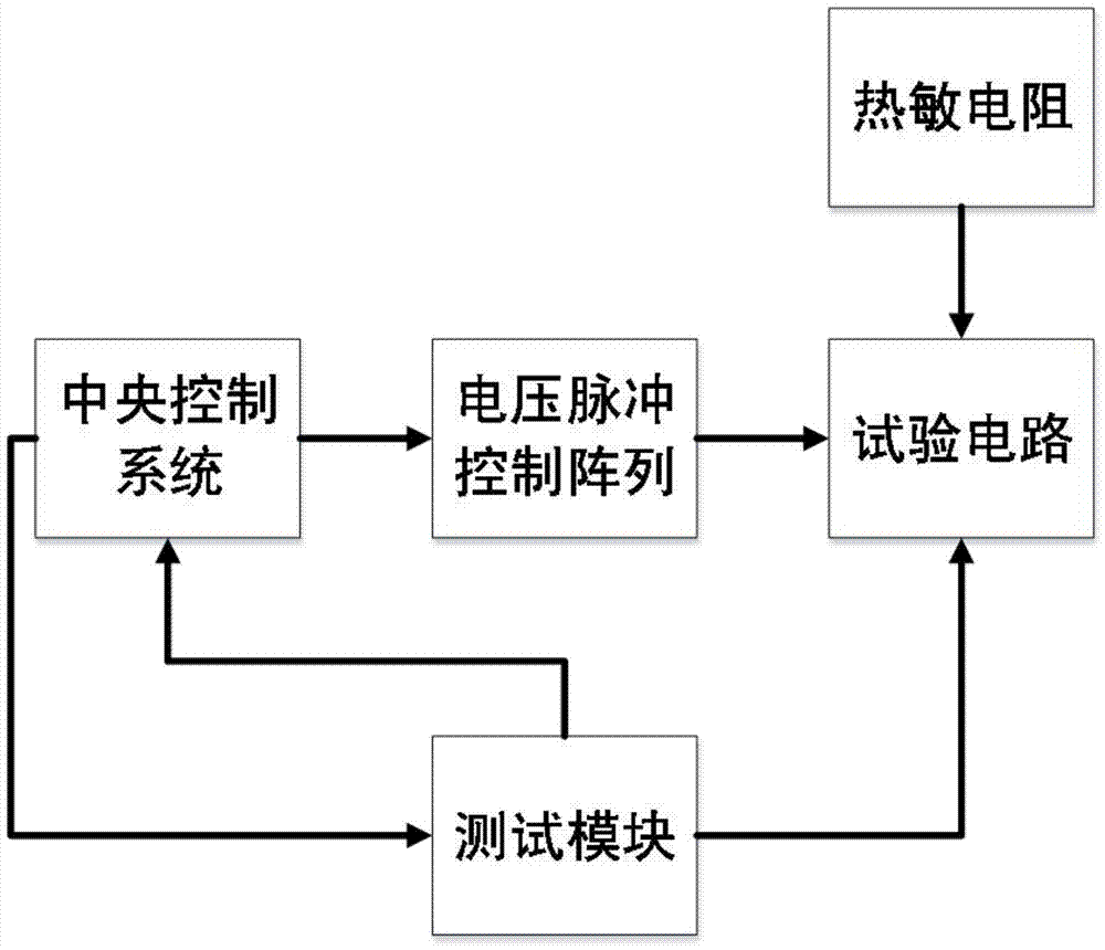
[0038] Embodiment 1 provided by the present invention is an embodiment of a device for continuously monitoring the resistance of a thermistor provided by the present invention, such as figure 1 Shown is the functional block diagram of a kind of thermistor resistance continuous electric cycle monitoring device provided by the present invention, by figure 1 It can be seen that the device includes: a central control system, a voltage pulse control array, a test module and a test circuit.
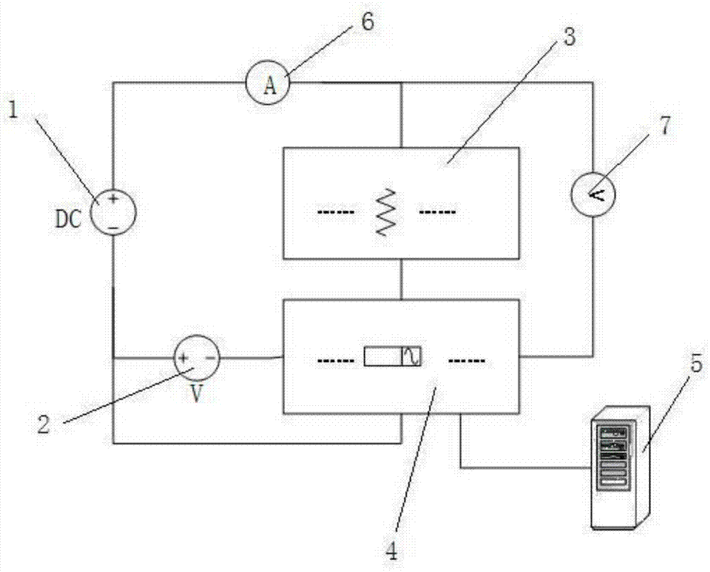
[0039] The test circuit includes a DC power supply and a thermistor array, the thermistor array includes at least two parallel thermistors, and the DC power supply provides DC power to each thermistor.
[0040] The test module includes an ammeter and a voltmeter to measure the total current and the total voltage of the thermistor array respectively.
[0041] The voltage pulse control array includes a voltage pulse generator and a relay array, and the relay array includes at least two relays. ...
Embodiment 2
[0048] Embodiment 2 provided by the present invention is an embodiment of a method for continuously monitoring the resistance of a thermistor provided by the present invention. The method includes:
[0049] In step 1, the DC power supply is connected and provides power to at least two thermistors connected in parallel, and the total voltage and current of the thermistors connected in parallel are measured in real time.
[0050] In step 2, each thermistor is connected to the corresponding relay, each thermistor is connected in series with the corresponding relay, and the voltage pulse generator is connected to the thermistor through the relay.
[0051] Step 3, the central control system sends a test command, and the control is connected to each relay in turn. At any time, only one relay is in the connected state, and the control voltage pulse generator generates a pulse voltage, which acts on the thermistor corresponding to the connected relay, and measures in real time The tot...
PUM
 Abstract
Description
Claims
Application Information
 - R&D
- Intellectual Property
- Life Sciences
- Materials
- Tech Scout
- Unparalleled Data Quality
- Higher Quality Content
- 60% Fewer Hallucinations
Browse by: Latest US Patents, China's latest patents, Technical Efficacy Thesaurus, Application Domain, Technology Topic, Popular Technical Reports.
© 2025 PatSnap. All rights reserved.Legal|Privacy policy|Modern Slavery Act Transparency Statement|Sitemap|About US| Contact US: help@patsnap.com