Remote automatic monitoring system for generating set

A technology of automatic monitoring system and generator set, which is applied in the direction of electrical program control, general control system, control/regulation system, etc.

Inactive Publication Date: 2016-01-20
成都安美科燃气技术股份有限公司
View PDF6 Cites 3 Cited by
  • Summary
  • Abstract
  • Description
  • Claims
  • Application Information

AI Technical Summary

Problems solved by technology

[0003] The technical problem to be solved by the present invention is to overcome the existing defects and provide a remote automatic monitoring system for generator sets. Aiming at the problems of on-site manual control and monitoring of existing gas-fired generator sets, a Communication, and the signal is transmitted in the form of optical fiber, and at the same time, functions such as emergency stop of the unit are realized on the hardware, so as to monitor and control the online status of the generator set

Method used


Image

  • Remote automatic monitoring system for generating set

Examples


Embodiment

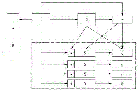
[0020] Example: such as figure 1 As shown, the present invention provides a remote automatic monitoring system for a generator set, including an engine electronic control module 4, a generator set controller 2, a PLC1 and a touch screen 7, the PLC1 is connected to the touch screen 7 through an optical fiber attachment, and the touch screen 7 is electrically connected to the storage device 8 Connection, PLC1 is respectively connected to generator set controller 2 and relay 3 through signal wires, generator controller 2 is respectively connected to engine 5, engine electronic control module 4, generator 6 and relay 3 through signal wires, relay 3 is connected through signal wires Connect with engine 5 and generator 6 respectively.

[0021] The engine electronic control module 4 is electrically connected to the engine 5 , and the engine 5 is electrically connected to the generator 6 . The number of the engine electronic control module 4 , the engine 5 and the generator 6 is the ...


PUM


Abstract

The invention provides a remote automatic monitoring system for a generating set. The remote automatic monitoring system for a generating set comprises an engine electric control module, a generating set controller, a PLC and a touch screen, wherein the PLC is connected with the touch screen through a fiber accessory; the touch screen is electrically with storage equipment; the PLC is connected with the generating set controller and a relay through a signal line; the generating set controller is connected with the engine, the engine electric control module, a generator and the relay through a signal line; and the relay is connected with the engine and the generator through a signal line. For solving the problem for on-site manual control and monitoring of a current gas generating set, the remote automatic monitoring system for a generating set establishes communication between a programmable controller and the generating set controller and transmits signals in the fiber mode, and at the same time realizes the function for sudden stop of the set on the hardware so as to realize monitoring and control of the on-line state of the generating set.

Description

technical field [0001] The invention relates to an automatic monitoring system for a generating set, in particular to an automatic monitoring system for a gas generating set. Background technique [0002] The existing gas-fired generator set adopts the on-site manual control mode, that is, a controller is installed next to the unit to realize the control of the unit and monitor its status, and the functions of starting, stopping, opening and closing of the unit need to be manually realized next to the unit. However, due to factors such as high noise next to the unit and many unexpected conditions, the operators cannot stay on site for a long time to monitor the status. If an accident occurs on site, it will cause losses to the personal safety of the operators and seriously affect the production work. Contents of the invention [0003] The technical problem to be solved by the present invention is to overcome the existing defects and provide a remote automatic monitoring sy...

Claims


Application Information

Patent Timeline
Patent Type & Authority Applications(China)
IPC IPC(8): G05B19/05
CPCG05B19/058G05B2219/25268
Inventor 施崇槐郑义豪王刚邹敏
Owner 成都安美科燃气技术股份有限公司
Why Eureka
Try Eureka