Drive structure and control method of switched reluctance motor based on three-level inverter

A technology of switched reluctance motors and three-level inverters, applied in the direction of AC motor control, control systems, electrical components, etc., can solve the problems of not being able to adapt to different working conditions, restricting control flexibility, and being unable to adjust in real time, to achieve The effect of improving safety and reliability, reducing difficulty of selection, and reducing costs

Active Publication Date: 2018-01-09
HEFEI UNIV OF TECH
View PDF6 Cites 0 Cited by
  • Summary
  • Abstract
  • Description
  • Claims
  • Application Information

AI Technical Summary

Problems solved by technology

[0007] 1. The existing topology only has three working states: power supply voltage excitation, reverse power supply voltage demagnetization, and zero-voltage freewheeling circuit. Changing the excitation voltage or demagnetization voltage can only be done by changing the power supply voltage, which cannot adapt to different working states. , different speed requirements
[0008] 2. The improved topology mainly increases the operating voltage by adding additional capacitors. Although the circuit operating mode is increased, the mutual interference between the front and rear phases of the motor greatly restricts the control flexibility.
[0009] 3. Some boost working states have too many restrictions and cannot be adjusted in real time according to control requirements
[0010] 4. The withstand voltage value of power devices is greatly improved, which increases the cost

Method used


Image

  • Drive structure and control method of switched reluctance motor based on three-level inverter
  • Drive structure and control method of switched reluctance motor based on three-level inverter
  • Drive structure and control method of switched reluctance motor based on three-level inverter

Examples


Embodiment Construction

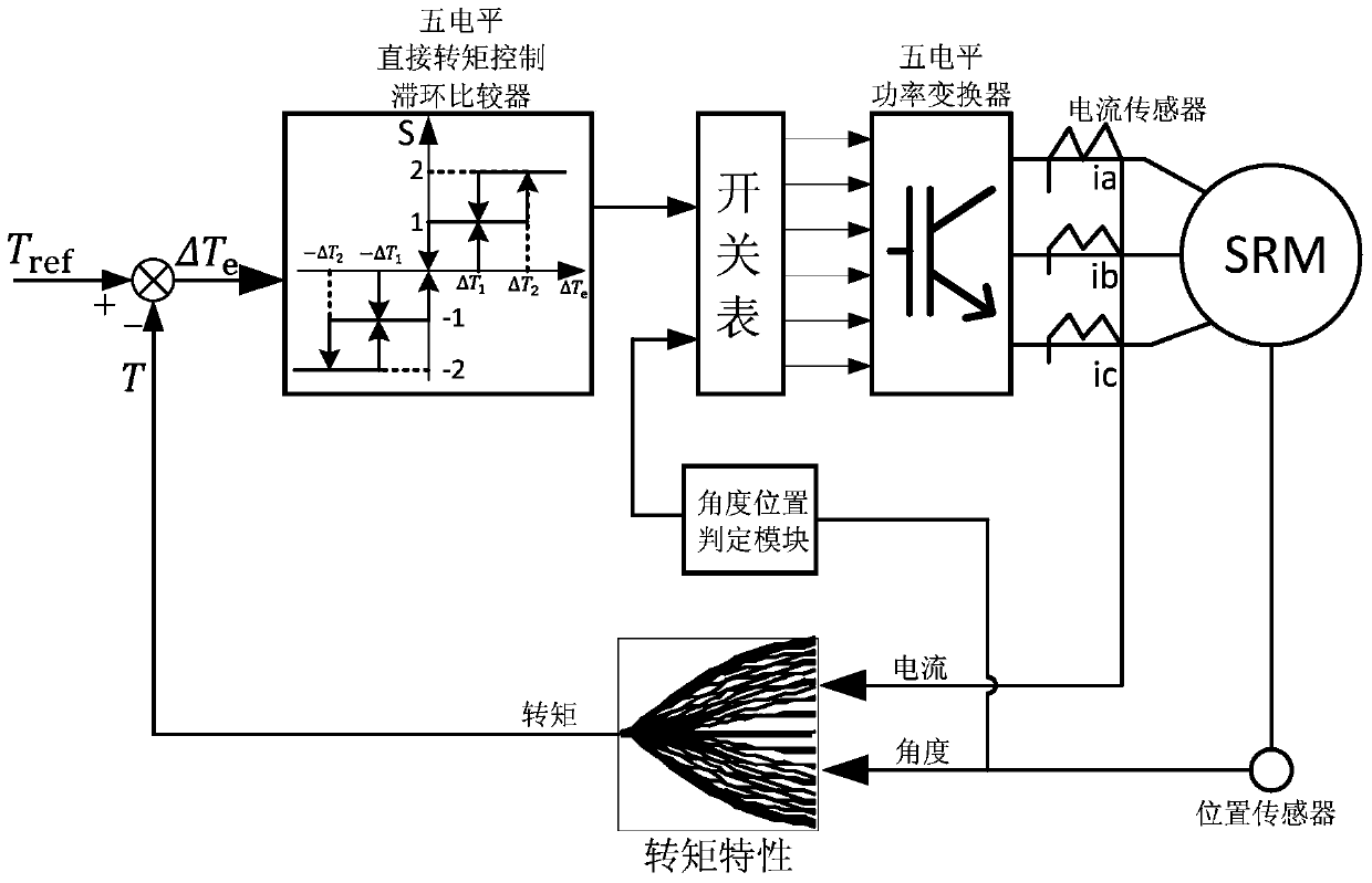
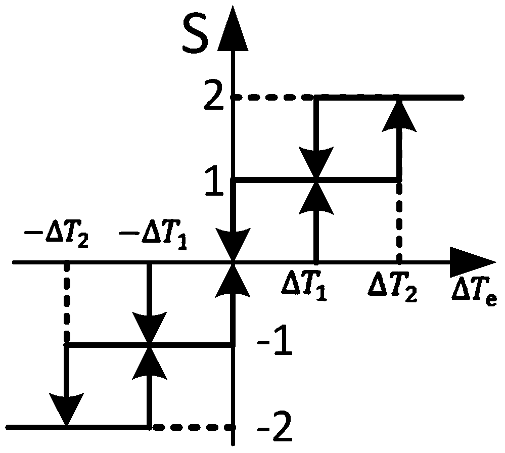
[0063] Combine below figure 1 and image 3 Illustrate the specific embodiment of the present invention:

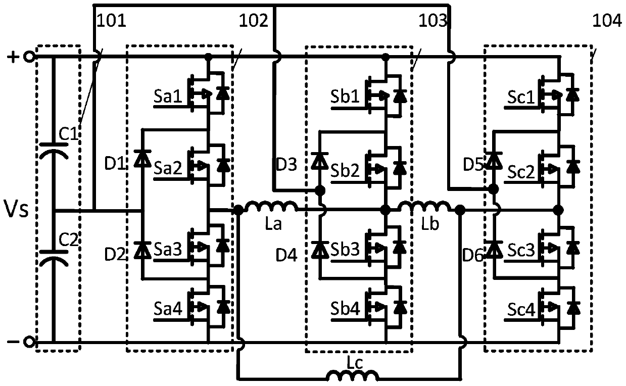
[0064] The driving structure of a switched reluctance motor based on a three-level inverter described in this embodiment is as follows: figure 1 As shown, it includes a power supply Vs, a switched reluctance motor phase A winding La, a switched reluctance motor phase B winding Lb, a switched reluctance motor phase C winding Lc, a capacitor module 101, a first bridge arm 102, and a second bridge arm 103 , the third bridge arm 104;

[0065] Figure 1 ~ Figure 3 The middle symbols respectively represent: Vs is the input power supply, which is the main power supply for the motor; Sa1, Sa2, Sa3, and Sa4 are the four switching tubes with anti-parallel diodes of the first bridge arm 102; Sb1, Sb2, Sb3, and Sb4 are Four switch tubes with anti-parallel diodes in the second bridge arm 103; Sc1, Sc2, Sc3, Sc4 are four switch tubes with anti-parallel diodes in the third bridge arm...


PUM


Abstract

The invention discloses a switched reluctance motor drive topology based on a three-level inverter. The switched reluctance motor winding is combined with the three-level inverter, and the two-phase windings of the switched reluctance motor share a three-level inverter. The bridge arm of the transformer, the three-phase windings are connected end to end, and a new topology is obtained. Considering that the torque ripple is mainly generated in the commutation area, the traditional topology has larger ripple due to fewer working modes. However, the topology proposed in the present invention has 9 different modes when working in a single phase. In the two-phase overlapping area, there are 27 combined modes. Different working states correspond to different phase voltages. You can choose the optimal state and change the torque waveform according to your needs, which greatly improves the control freedom, reduces the torque ripple, and improves the torque. The advantage of the present invention is that a five-level circuit is proposed, so that each phase winding has good applicability and flexibility in high speed, low speed, excitation, demagnetization and the like. Effectively reduce the switching frequency, reduce the switching loss, increase the output torque of the switched reluctance motor, and smooth the torque ripple.

Description

technical field [0001] The invention relates to a switched reluctance motor drive system, in particular to a power conversion topology structure of a switched reluctance motor for an electric vehicle. Background technique [0002] A switched reluctance motor (Switched Reluctance Motor, SRM) only has windings on the stator, and the rotor is made of silicon steel sheets, which has a strong structure and low cost. It has a wide speed range, large starting torque, the torque direction is independent of the phase current, flexible control and high efficiency; it can regenerative braking and energy recovery, so it has gradually received attention in the field of electric vehicles. Now it has been used in the textile industry, aviation and household appliances. However, due to the double salient pole structure of the switched reluctance motor and the nonlinearity of the magnetic field, the torque ripple is relatively large, and the problems of vibration and noise are prominent. I...

Claims


Application Information

Patent Timeline
Patent Type & Authority Patents(China)
IPC IPC(8): H02P25/092
Inventor 马铭遥常中意杨晴晴李飞张兴
Owner HEFEI UNIV OF TECH
Why Eureka
Try Eureka