Communication method and system based on optical information and device

A technology of optical information and sub-device, which is applied in the field of visible light communication, can solve the problems of low positioning accuracy and unsatisfactory requirements for long-distance positioning, and achieve the effect of flexible system configuration

Inactive Publication Date: 2016-01-20
尹军
View PDF4 Cites 6 Cited by
  • Summary
  • Abstract
  • Description
  • Claims
  • Application Information

AI Technical Summary

Problems solved by technology

[0003] Note that in the above process, the receiving end judges the distance between itself and the light source according to the luminosity of the measured signal point. Before starting the indoor positioning measurement, it must first quantitatively determine the attenuation law of the optical signal with distance, that is, determine the luminosity change curve , and then judge the distance according to

Method used


Image

  • Communication method and system based on optical information and device
  • Communication method and system based on optical information and device
  • Communication method and system based on optical information and device

Examples


Embodiment Construction

[0020] The technical solutions of the present invention will be described in detail below in conjunction with the accompanying drawings and specific embodiments.

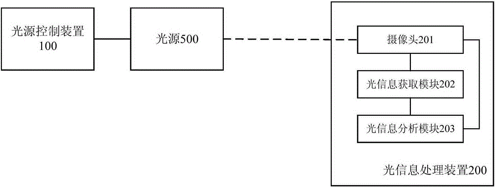
[0021] figure 1 It shows the architecture diagram of the optical communication system according to the embodiment of the present invention, which includes a light source control device 100 and an optical information processing device 200. The light source control device 100 controls the light source 500 to make the light source 500 emit specific optical information. The optical information processing device 200 The camera 201 in the camera shoots a video of the light source 500, the optical information acquisition module 202 obtains the required information from the captured video, and then the optical information analysis module 203 analyzes the information to obtain the content of the optical information emitted by the light source 500.

[0022] Specifically, in the embodiment of the present invention, the light s...


PUM


Abstract

The invention discloses a control device for a light source. The control device is used for controlling one or more light sources in order that each light source in the one or more light sources emits light according to a predetermined mode, wherein the predetermined mode includes at least two states of a single light source and the duration of each state in the at least two states. The invention also discloses a control method for the light source, a device and a method for processing optical information, a system for processing the optical information, and a light communication system. Thus, an optical information interaction between an emitting end and a receiving end can be realized conveniently.

Description

technical field [0001] The present invention relates to the technical field of visible light communication, in particular to a communication method, device and system based on optical information. Background technique [0002] Visible light communication technology (VisibleLightCommunication) uses light in the visible light band as an information carrier, and does not use optical fiber and other wired channel transmission media, but directly transmits optical signals in the air. The application of visible light communication technology is more common in visible light indoor positioning technology. The common indoor positioning method based on RSS (Received Signal Strength) uses LED (Light Emitting Diode, light-emitting diode) to fix the position and facilitate mass use. Light source, according to the principle that the optical power of the receiving end decreases regularly with the increase of the distance, the distance between the transmitting end and the receiving end can ...

Claims


Application Information

Patent Timeline
IPC IPC(8): H04B10/116
Inventor 尹嘉峥尹军
Owner 尹军
Why Eureka
Try Eureka