

Half shell bearing
A technology for bearings and bearing shells, applied in the direction of bearings, bearing components, shafts and bearings, etc., can solve problems affecting the functionality of half-shell bearings, damage to bearing shells or cages, etc.
- Summary
- Abstract
- Description
- Claims
- Application Information
AI Technical Summary
Problems solved by technology
Method used
Image

Examples
Embodiment Construction
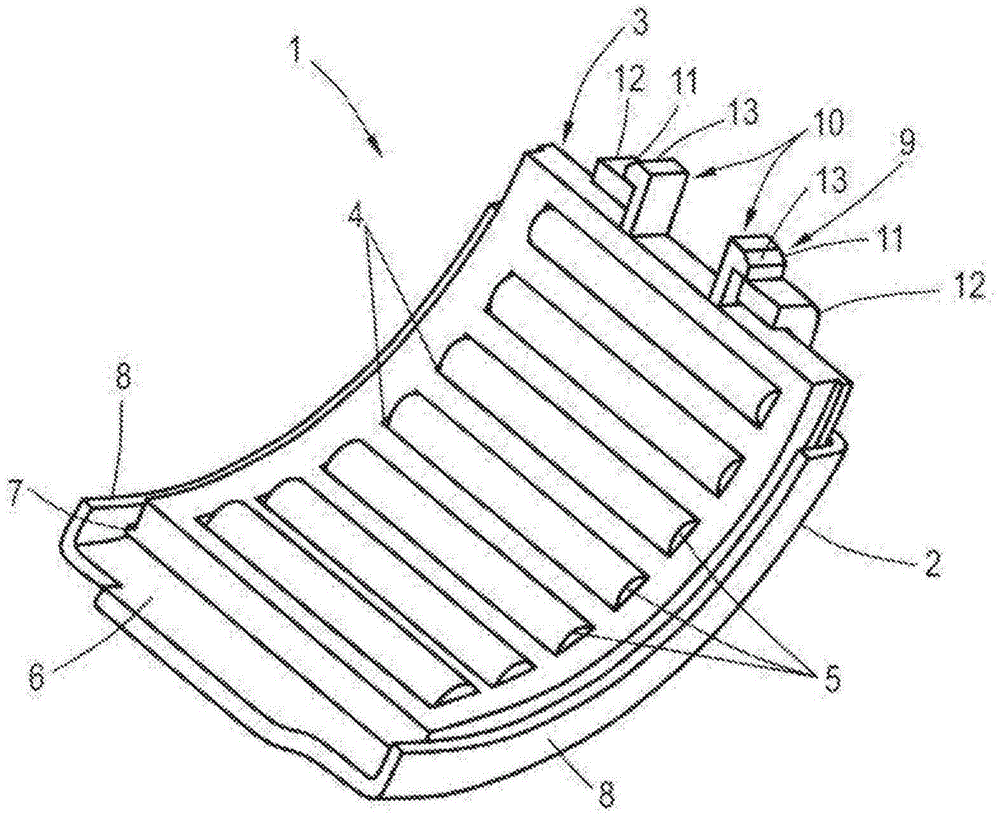
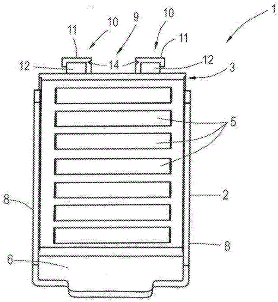
[0022] figure 1 A half-shell bearing 1 according to the invention is shown in a first embodiment, comprising a bearing shell 2 , usually made of metal or sheet metal, in which a cage 3 , usually made of plastic, is accommodated. In the cage, rolling bodies 5 in the form of rollers are accommodated in the respective receptacles 4 . When the half-shell bearing 1 according to the invention is assembled via the bearing shell 2 on a housing or other component, usually by press-fitting or the like, the rolling bodies 5 roll on the inside 6 of the half-shell 2 forming the running surface. In the assembled position or in operation, the cage 3 can be moved along the raceway defined by the curved half-shells 2 , so that a component mounted via the rolling elements 5 , such as a brake lever or similar, pivots. The rod is supported accordingly.
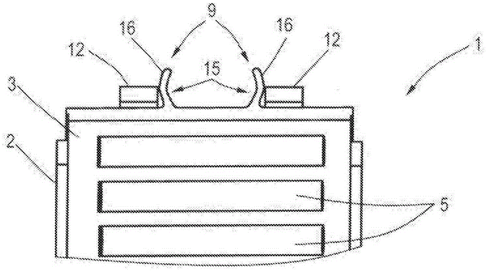
[0023] On the one hand, the cage 3 is radially stopped to prevent it from falling off. For this reason, corresponding axially protruding tabs ...
PUM
 Abstract
Description
Claims
Application Information