
Mixing device for gas-liquid two-phase annular flow jet flow and main flow gas

An annular flow, gas-liquid mixer technology, which is applied in the directions of liquid injection devices and injection devices, can solve the problems of complex flow state, compact design and economic limitations, and no gas-liquid two-phase jet form is found. Achieve the effect of intensifying crushing and atomization, enhancing instability, and enhancing blending

Inactive Publication Date: 2016-01-27
XI AN JIAOTONG UNIV
View PDF6 Cites 8 Cited by
  • Summary
  • Abstract
  • Description
  • Claims
  • Application Information

AI Technical Summary

Problems solved by technology

Due to the existence of various flow patterns of gas-liquid two-phase flow and the complexity of the flow state, no gas-liquid two-phase flow jet has been found at home and abroad.
In order to facilitate control, in the actual blending process, the gas jet and the liquid jet are usually introduced into the blending system by two sets of supply systems, which has brought great limitations to the compact design and economical efficiency of the system equipment

Method used


Image

  • Mixing device for gas-liquid two-phase annular flow jet flow and main flow gas
  • Mixing device for gas-liquid two-phase annular flow jet flow and main flow gas
  • Mixing device for gas-liquid two-phase annular flow jet flow and main flow gas

Examples


Embodiment

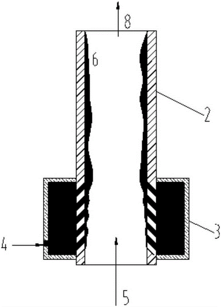
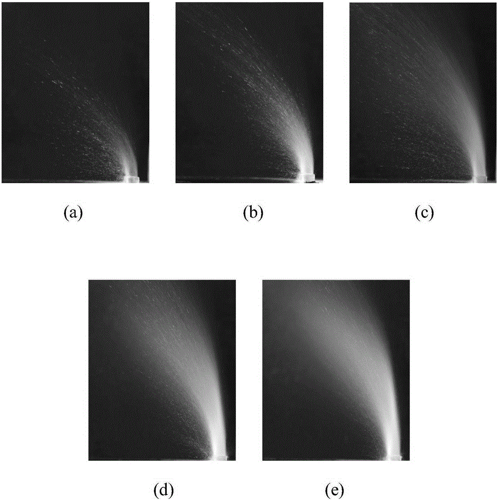
[0043] The inner cavity of the mainstream pipeline is a rectangular cavity with a cross-sectional size of 180×180mm. The mainstream gas is provided by an air compressor, and the velocity range in the experiment is 2-14.5m / s. The inner diameter of the annular flow jet tube is 10mm, and the length is 1.5m. The gas and liquid enter the annular flow through the gas-liquid mixer (the annular flow generator, the structure is a honeycomb with small holes on the wall, and the diameter of the small holes is 200um). The jet tube forms a gas-liquid two-phase annular flow jet. Among them, the gas flow rate range is 5.65-19.78m 3 / h (the equivalent superficial gas velocity range is about 20-70m / s), and the liquid working medium flow rate range is 14-114kg / h (the equivalent superficial liquid velocity range is about 7-12.7m / s). The camera is used to photograph the jet atomization process and atomization structure, and the Malvern particle size analyzer is used to measure the particle size ...


PUM


Abstract

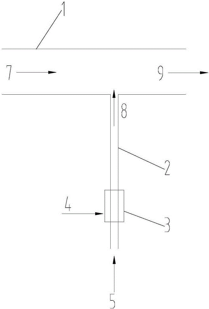
The invention discloses a mixing device for gas-liquid two-phase annular flow jet flow and main flow gas. The mixing device comprises a main flow pipeline and an annular flow jet flow pipe communicated with the side wall of the main flow pipeline. A gas-liquid mixer is arranged on the upper reaches of the annular flow jet flow pipe in the circumferential direction. Inlets of the gas-liquid mixer are communicated with honeycomb-shaped holes formed in the side wall of the annular flow jet flow pipe. When the mixing device is used, a liquid working medium enters the gas-liquid mixer and then enters the annular flow jet flow pipe through the honeycomb-shaped holes. Gas-liquid two-phase annular flow is formed after the liquid working medium is mixed with a gas working medium in the annular flow jet flow pipe, and a liquid film is formed on the inner wall of the annular flow jet flow pipe. After the gas-liquid two-phase annular flow jet flow and the main flow gas in the main flow pipeline are mixed, atomization is completed to form an atomized droplet cluster. According to the mixing device, in the jet flow mixing process, the interaction between the gas-liquid two-phase annular flow jet flow and the main flow gas is used; a good atomization effect can be achieved through the gas-liquid two-phase annular flow jet flow, and accordingly good mixing between the gas-liquid two-phase annular flow jet flow and the main flow gas is achieved.

Description

Technical field: [0001] The invention relates to a technology for optimizing gas-liquid jet mixing structure, in particular to a mixing device for gas-liquid two-phase annular flow jet and mainstream gas. Background technique: [0002] The mixing of liquid jet and air flow is an important way to enhance multiphase flow and heat transfer, and has great application requirements in civil and national defense fields. The interaction between the jet and the main fluid induces a multi-scale complex vortex structure in the flow field, and uses the entrainment and entrainment between the fluids to promote the mixing of components and heat to achieve the purpose of uniform mixing. For example, the common combustion technology in the field of energy and power engineering uses jets to fully mix fuel and oxidant (such as air) to improve combustion efficiency; another example is the common chemical reaction technology in the chemical industry, which often uses jet feeding to promote rapi...

Claims


Application Information

Patent Timeline
Patent Type & Authority Applications(China)
IPC IPC(8): B05B7/04
CPCB05B7/0416
Inventor 张海滨白博峰赵中闯
Owner XI AN JIAOTONG UNIV
Learn More