Braking spiral paint spraying equipment

A painting equipment, spiral technology, applied in the field of braking spiral painting equipment, to achieve the effect of ensuring integrity

Inactive Publication Date: 2016-01-27
广州贝铂涂料有限公司
View PDF7 Cites 8 Cited by
  • Summary
  • Abstract
  • Description
  • Claims
  • Application Information

AI Technical Summary

Problems solved by technology

In the specific operation, due to the shape factor, in order to save materials and speed up the spraying speed, the spiral spraying method has been used when spraying the upper surface of the circular plate. However, due to the size of the surface area of ​​the parts to be sprayed, often Requires braking while in use, but conventional auger spray equipment does not perform well with automatic braking

Method used


Image

  • Braking spiral paint spraying equipment
  • Braking spiral paint spraying equipment
  • Braking spiral paint spraying equipment

Examples


Embodiment Construction

[0019] In order to make it easy to understand the technical means, creative features, achieved goals and effects of the present invention, the present invention is further described below.

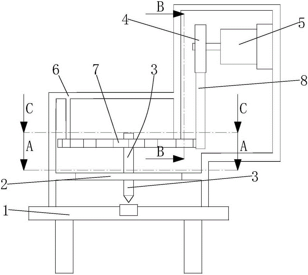
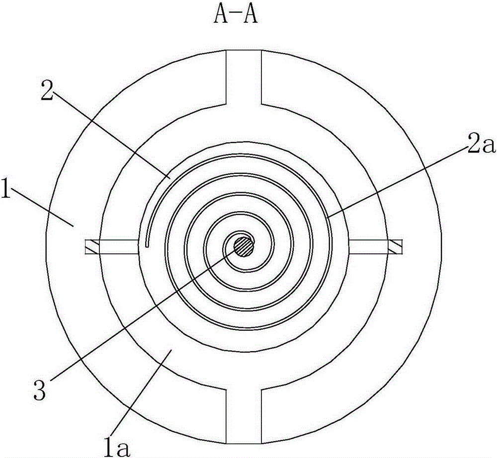
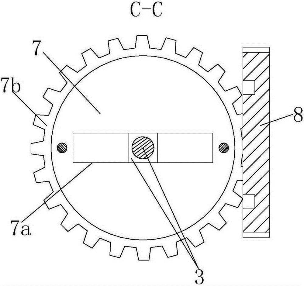
[0020] like Figure 1 to Figure 4 As shown, a braking spiral paint spraying equipment mainly includes a workbench 1, and a placement groove 1a is provided in the center of the workbench 1, and a circular No. 1 control frame 2 is provided at the upper end of the placement groove 1a. The No. 1 control rack 2 is provided with a No. 1 spiral groove 2a, and the No. 1 control rack 2 is provided with a No. 2 control rack 7 directly above the No. 2 control rack 7. In the rectangular groove 7a of the center of mass, a spray gun 3 is slidably installed in the rectangular groove 7a along the length direction, and the lower end of the spray gun 3 extends through the No. 1 spiral groove 2a.

[0021] The outer arc end surface of the No. 2 control frame 7 is provided with a No. 1 spur gear 7b, the right...


PUM


Abstract

The invention relates to braking spiral paint spraying equipment which mainly comprises a workbench and a placing groove. A circular first control rack is arranged at the front upper end of the placing groove, and a first spiral groove is formed in the first control rack. A second control rack is arranged over the first control rack, and a rectangular groove with the same centroid as the second control rack is formed in the second control rack. A spray gun is mounted in the rectangular groove in a sliding mode in the length direction, and the lower end of the spray gun extends to penetrate through the first spiral groove. A first straight gear ring is arranged on the outer arc-shaped end face of the second control rack, and a compass is arranged on the right portion of the second control rack. A second spiral groove is formed in the left end of the compass, and any gear tooth of the first straight gear ring is clamped into the second spiral groove. A second straight gear ring is arranged on the periphery of the compass and engaged with a gear which is connected with a motor. According to the braking spiral paint spraying equipment, the spiral radius of the spiral grooves is controlled to control the rotating angle of the second control rack so that the travel path of the spray gun in the first spiral groove can be effectively changed, and the effect of braking in the spraying process is realized.

Description

technical field [0001] The invention relates to the field of spraying and decoration equipment, in particular to a braking spiral paint spraying equipment. Background technique [0002] Generally speaking, some steel parts need to be coated with a layer of glue paint on the surface after they are completely processed, so as to protect the parts to a certain extent. In the specific operation, due to the shape factor, in order to save materials and speed up the spraying speed, the spiral spraying method has been adopted when spraying the upper end face of the circular plate, but due to the size of the surface area of ​​the parts to be sprayed, often Braking is required when in use, but traditional spiral spray equipment does not do automatic braking very well. SUMMARY OF THE INVENTION [0003] In order to solve the above two deficiencies, the present invention proposes a braking spiral paint spraying device for braking during the spraying process. [0004] A braking spiral...

Claims


Application Information

Patent Timeline
Patent Type & Authority Applications(China)
IPC IPC(8): B05B13/04
CPCB05B13/0421
Inventor 付建邹洪
Owner 广州贝铂涂料有限公司
Why Eureka
Try Eureka