Cutter rest assembly

A tool holder and component technology, applied in the field of CNC lathes, can solve problems such as inability to effectively satisfy users, inability to satisfy, and poor reliability of locking structures

Active Publication Date: 2016-01-27
上海西马特机械制造有限公司
View PDF10 Cites 4 Cited by
  • Summary
  • Abstract
  • Description
  • Claims
  • Application Information

AI Technical Summary

Problems solved by technology

[0002] As we all know, the cutting strength of small or micro CNC inclined guide rail lathes is closely related to the design of the tool holder assembly. The existing tool holder assembly has problems in various aspects such as structural design, positioning accuracy, cutting strength, etc., and

Method used


Image

  • Cutter rest assembly
  • Cutter rest assembly
  • Cutter rest assembly

Examples


Embodiment Construction

[0035] In order to make the technical means, creative features, goals and effects achieved by the present invention easy to understand, the present invention will be further described below in conjunction with specific embodiments.

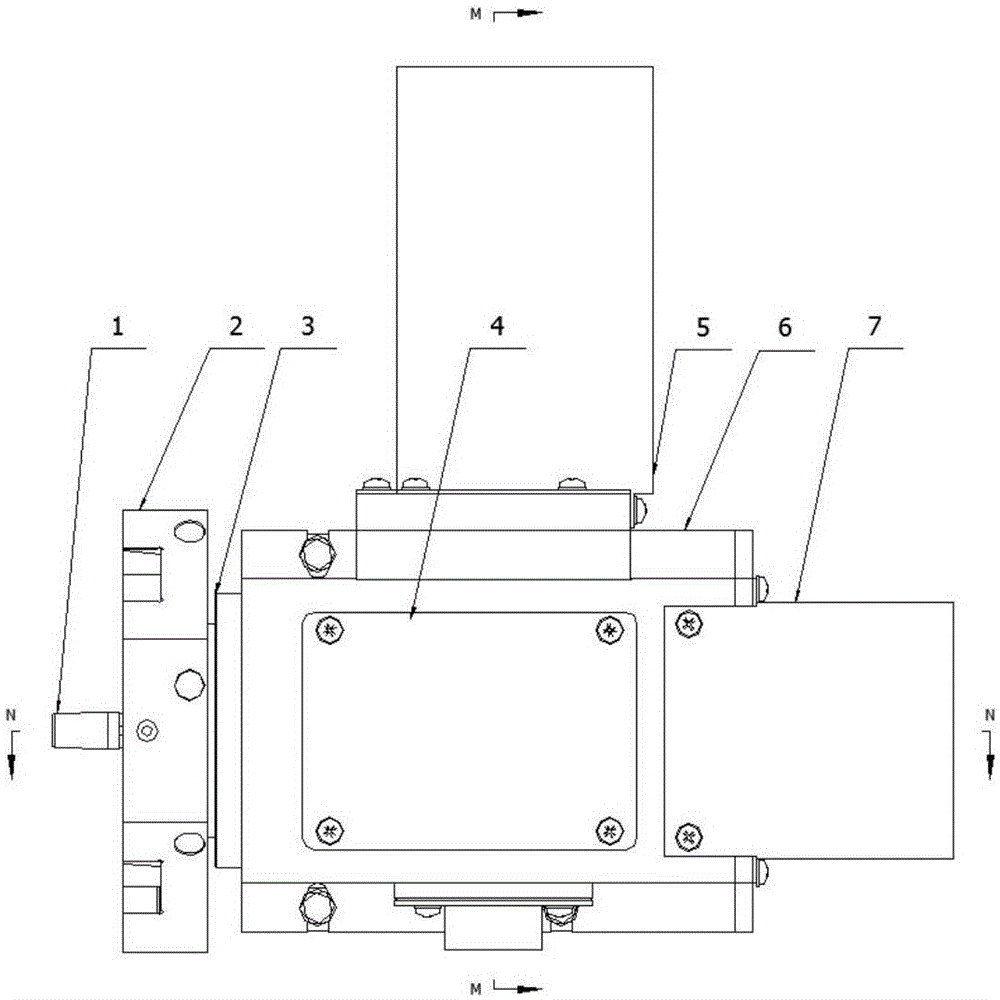
[0036] Such as Figure 1-10 As shown, the tool post assembly includes: a cutter head part A, a main shaft part B, a worm part C, a tool post box part D, and an ejection mechanism part E installed on the tool post box part.

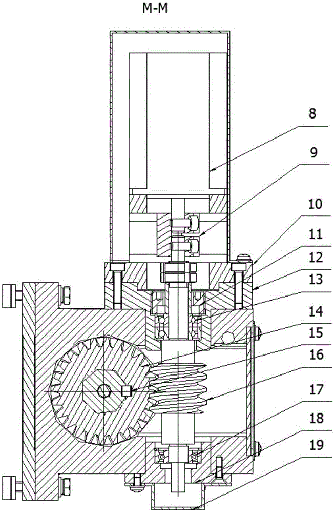
[0037] see Figure 10 , The ejection mechanism part includes: rear cover plate, permanent magnet synchronous motor, small motor fixing plate, pinion II, metal joint, back cover, pinion I and threaded ejector rod and other structural components.

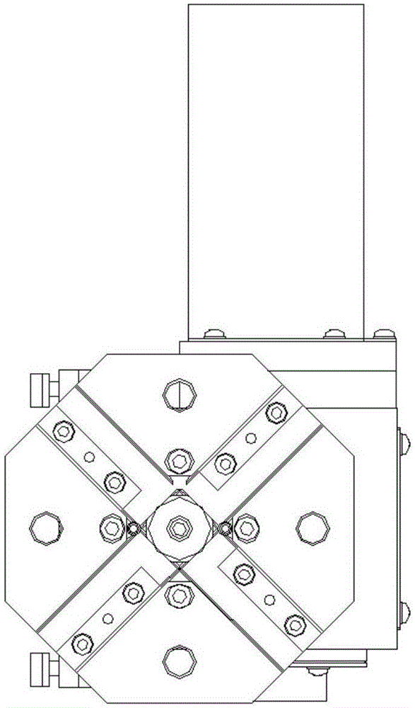
[0038] see Image 6 , the cutterhead part A includes an eight-station cutterhead 2, and the eight-station cutterhead is provided with a taper chuck adapter 1, a pressing block IA1, and a pressing block IIA2.

[0039] The main shaft part B connected to the cutter head part A include...


PUM


Abstract

The invention discloses a cutter rest assembly. The cutter rest assembly comprises a cutter disc part, a main shaft part, a worm part, a cutter rest box body part and an ejection mechanism part, wherein a fixed end tooth I is installed at the front end of the cutter rest box body; a fixed end tooth II matched with the fixed end tooth I is installed at the front end of the main shaft and connected with a main shaft through keys; a moving end tooth is further installed on the front portion of the main shaft and connected with the main shaft through a straight pin shaft and a key and achieves axial movement through an ejection rod and a compression spring installed inside the main shaft; the end, far away from the cutter disc part, of the cutter rest box body is provided with a power driving mechanism for driving the ejection rod to rotate forwards and reversely. The cutter rest assembly is more useful for small or micro numeral control inclined guide rail lathes, and the positioning accuracy and cutting force are greatly improved compared with a square cutter frame. Primary positioning is achieved mainly through matching of an eight-equal-part ratchet wheel and a supporting foot assembly on the main shaft. Accurate positioning is achieved through meshing of the moving end tooth and the fixed end teeth. A worm has a self-locking function, and finally a cutter disc is fixed and used for machining a part.

Description

technical field [0001] The invention relates to the field of numerically controlled lathes, in particular to a tool holder assembly suitable for small and miniature numerically controlled inclined rail lathes. Background technique [0002] As we all know, the cutting strength of small or micro CNC inclined guide rail lathes is closely related to the design of the tool holder assembly. The existing tool holder assembly has problems in various aspects such as structural design, positioning accuracy, cutting strength, etc., and cannot effectively meet the needs of users. requirements, and for the locking structure of the cutter head after the tool is replaced in place, due to the disadvantages of the design, it cannot meet the above requirements, and there is also the problem of poor reliability of the locking structure. Contents of the invention [0003] The object of the present invention is to solve the above problems, and provide a tool holder assembly with simple structu...

Claims


Application Information

Patent Timeline
IPC IPC(8): B23B21/00
CPCB23Q1/03
Inventor 余国梁
Owner 上海西马特机械制造有限公司
Why Eureka
Try Eureka