
Low-noise submarine

A low-noise, submarine technology, applied in the direction of ships, underwater ships, special-purpose ships, etc., can solve the problems of complex sound insulation, sound absorption or sound reduction structure, inability to achieve submarine sound reduction, poor noise reduction effect, etc., and achieve sound insulation effect. Excellent, easy-to-implement, zero-cost results

Inactive Publication Date: 2016-01-27
李建明 +1
View PDF8 Cites 7 Cited by
  • Summary
  • Abstract
  • Description
  • Claims
  • Application Information

AI Technical Summary

Problems solved by technology

[0004] Although the above-mentioned numerous traditional sound insulation schemes can achieve a certain sound insulation effect, they still have the following deficiencies: (1) Sound insulation or sound absorption is only performed on a single or local noise source, and it is impossible to reduce the overall sound of the submarine. The noise effect is poor; (2) Various sound insulation, sound absorption or sound reduction structures are relatively complex, and the implementation requirements are relatively high

Method used


Image

  • Low-noise submarine
  • Low-noise submarine
  • Low-noise submarine

Examples


Embodiment 1

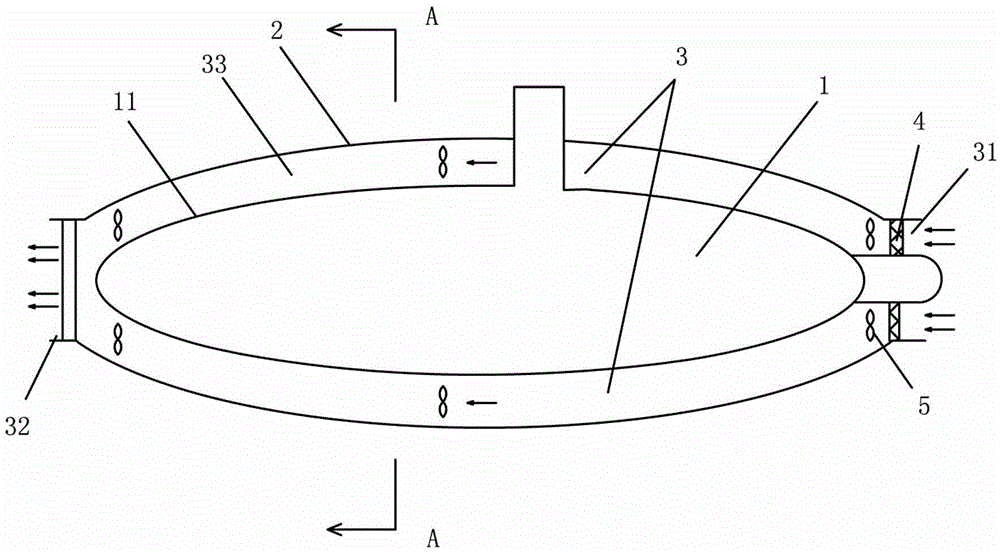
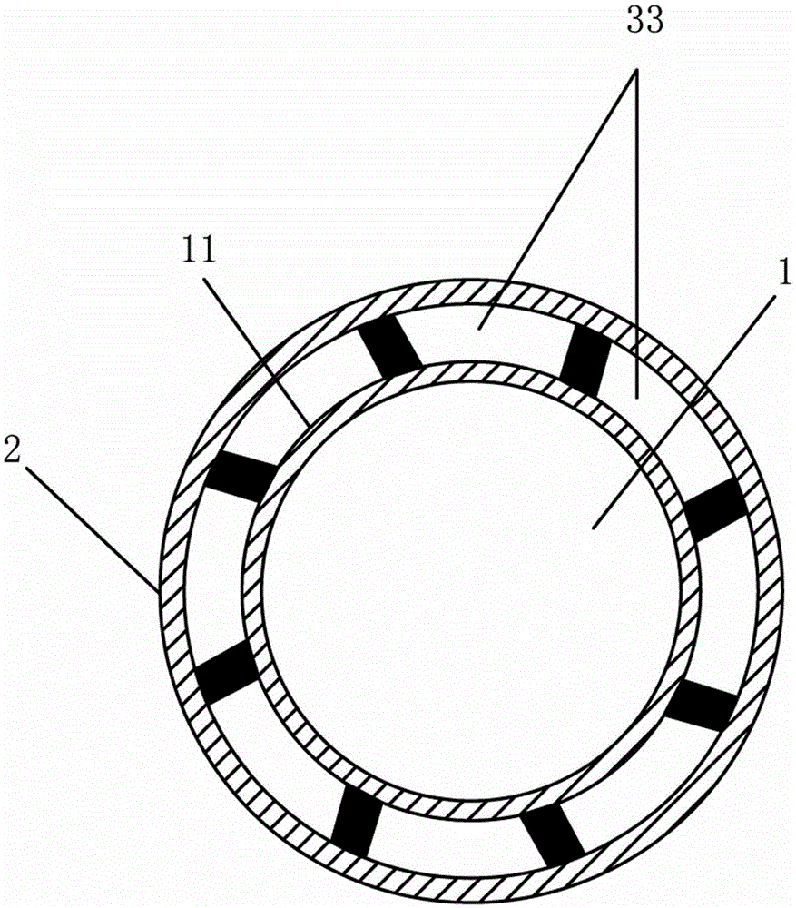
[0024] Embodiment one: if figure 1 and figure 2 As shown, a low-noise submarine includes a hull 1, and is characterized in that it also includes a sound-reducing shell 2, which is arranged on the outer wall 11 of the hull 1, and the distance between the hull 1 and the sound-falling shell 2 is There is a sound-reducing gap 3 between them, the sound-reducing gap 3 is liquid flowing through the gap 33, and the liquid flowing through the gap 33 is a channel for sea water to flow through. Water port and 31 rear discharge ports 32 are arranged on the front end and the rear end of the hull 1 respectively.

[0025] In order to prevent impurities in the seawater from being introduced, a filter 4 is provided at the front water inlet 31 where the liquid flows through the gap 33 .

[0026] In order to further improve the flow of seawater in the soundproof gap 3, and even significantly reduce the water resistance, the liquid flows through the gap 33 and is provided with a drainage prope...

Embodiment 2

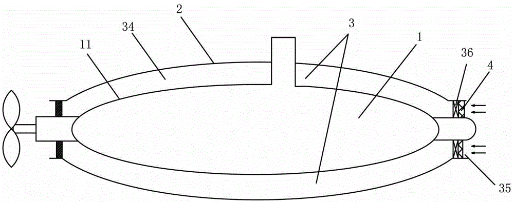
[0029] Embodiment two: if image 3 As shown, this embodiment is similar to the first embodiment above, the difference is: the liquid storage gap 34 can be a seawater storage airtight chamber, the seawater storage airtight chamber has a water exchange port 35, and the water exchange port 35 is provided with a water exchange valve 36 Similarly, in order to prevent the impurity in the seawater from entering, the water exchange port 35 of the seawater storage airtight chamber is provided with a filter screen 4; After the seawater is released, close the water exchange valve 35, and the seawater is used as a sound insulation material; otherwise, when the submarine stops running, the seawater in the liquid storage gap 35 can be discharged through the water exchange valve 35; pusher propeller.


PUM


Abstract

The invention discloses a low-noise submarine. The low-noise submarine comprises a submarine body and is characterized by further comprising a silencing housing, wherein the silencing housing is arranged on the outer wall of the submarine body; a silencing gap exists between the submarine body and the silencing housing; and the silencing gap is a liquid storage gap or a liquid flowing gap. As the silencing housing is additionally arranged on the outer wall of the submarine body of the submarine, the liquid is stored in or flows through the silencing gap between the silencing housing and the submarine body so that a silencing layer is formed between the outer wall of the submarine body (in operation) and seawater; therefore, the integral silencing effect of the submarine is realized and the noise reducing effect is obviously improved. And moreover, the invention is advantaged in that the low-noise submarine is simply structured and simple to implement; the sound insulating effect of the low-noise submarine is extremely perfect by using seawater as a sound insulating material; and the submarine can be in the seawater during operation so that the seawater is easy to collect and zero cost is realized.

Description

technical field [0001] The invention relates to the technical field of submarines, in particular to a low-noise submarine. Background technique [0002] The noise generated during the operation of the submarine is the most important factor affecting the concealment of the submarine underwater. The main sources of the noise of the submarine include: (1) the air noise generated by the mechanical operation in the cabin; (2) the vibration of the mechanical components in the hull Structural noise transmitted in the structure; (3) fluid dynamic noise caused by water flow through the hull and protrusions and various systems in the boat; (4) rotational noise of the propeller, etc. Among the above-mentioned noise sources, mechanical equipment and propellers are the main noise sources. The noise is transmitted to the hull through the air in the submarine cabin, causing the submarine hull to vibrate and generate noise. [0003] At present, there are also some ways to solve noise: for ...

Claims


Application Information

Patent Timeline
Patent Type & Authority Applications(China)
IPC IPC(8): B63G8/00B63G8/34
Inventor 李建明李子业
Owner 李建明
Learn More