
Electric slitting machine

An electric and coupling technology, applied in the direction of hoisting device, hoisting device, etc., can solve the problems of complex assembly process, high production cost, inconvenient to carry, etc., and achieve the effect of avoiding separation from the screw, low production cost and easy assembly

Active Publication Date: 2016-01-27
JUNPENG SPECIAL EQUIP
View PDF4 Cites 0 Cited by
  • Summary
  • Abstract
  • Description
  • Claims
  • Application Information

AI Technical Summary

Problems solved by technology

At present, the existing slotters generally push the piston by hydraulic driving force, and then the piston drives the wedge block fixedly connected with the piston to push the spring plate inserted into the load to spread the load, so that the load is separated from the gap. However, due to At present, the existing slotters generally use hydraulic propulsion as the power source, and need to be equipped with a hydraulic station when in use, which leads to a complex design of the sealing structure of the slotter on the one hand, increasing the complexity of the slotter structure and production costs. High, complex assembly process; on the other hand, it must be equipped with a hydraulic station when using it, which is inconvenient to carry. The use of the slotter is greatly affected by the hydraulic station, and the slotter cannot work without the hydraulic station.

Method used


Image

  • Electric slitting machine
  • Electric slitting machine

Examples


Embodiment Construction

[0019] In the following, the present invention will be further described in conjunction with the accompanying drawings and specific embodiments, so as to understand more clearly the technical idea claimed in the present invention.

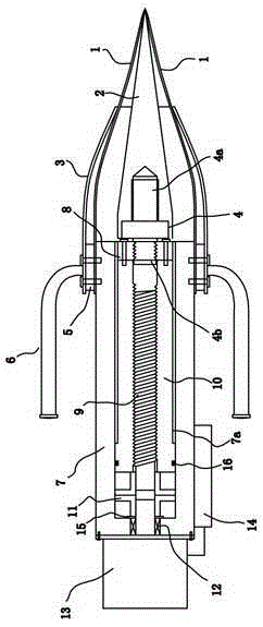
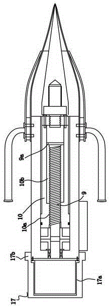
[0020] Such as figure 1 An embodiment of an electric slotter of the present invention is shown, including a spring plate 1, a wedge block 2, a spring plate holster 3, a stud bolt 4, a handle ring 5, a handle 6, a main housing 7, and a connecting nut 8. Screw rod 9, screw sleeve 10, coupling 11, bearing 12, micro motor 13 and rechargeable battery 14, the main housing 7 is provided with a hollow chamber 7a, the front end of the hollow chamber 7a is open and the rear end is closed; the spring plate 1. Wedge block 2, spring plate holster 3 and handle ring 5 are installed on the front end of main housing 7, wedge block 2 is set inside spring plate 1, spring plate holster 3 is set outside spring plate 1, handle 6 is welded and fixed On the handle ring 5...


PUM


Abstract

The invention discloses an electric slitting machine which comprises a spring plate, a wedge-shaped block, a spring plate leather sheath, a double-ended bolt, a handle ring, a handle, a main housing, a connecting nut, a screw, a threaded sleeve, a shaft coupler, a bearing, a micro motor and a charging battery, wherein the micro motor is mounted at the rear end of the main housing; the output shaft of the micro motor is mounted on the bearing and is in transmission connection with the screw through the shaft coupler; the charging battery is electrically connected with the micro motor; the threaded sleeve is arranged between the inner wall of a hollow chamber and the screw, and is in threaded connection with the screw; the connecting nut is mounted at the front end of the threaded sleeve through a bolt; and a second connecting head of the double-ended bolt is fixedly connected with the connecting nut. According to the electric slitting machine, the micro motor drives the screw to horizontally move in an axial direction of the screw; the threaded sleeve drives the wedge-shaped block to move forwards to support and jack the spring plate; the micro motor is powered by a charging battery, so that electric control of the slitting machine is realized; and a hydraulic station is not required to arrange, so that the electric slitting machine is convenient in carrying, simple in structure, relatively low in production cost and easy to assemble.

Description

technical field [0001] The invention relates to a seam opener, in particular to an electrically controlled seam opener used to prop up and separate loads in various rescue and fire-fighting places so that sufficient gaps are separated between the loads. Background technique [0002] Slit slotters are generally used in various rescue and fire-fighting places, such as fire, flood, earthquake and other natural disasters, to support and separate the loads that need to be separated, such as stones and other heavy objects, so that enough space can be separated between the loads. gaps to ensure the smooth development of follow-up rescue work. At present, the existing slotters generally push the piston by hydraulic driving force, and then the piston drives the wedge block fixedly connected with the piston to push the spring plate inserted into the load to spread the load, so that the load is separated from the gap. However, due to At present, the existing slotters generally use hyd...

Claims


Application Information

Patent Timeline
Patent Type & Authority Applications(China)
IPC IPC(8): B66F19/00
Inventor 郑东升
Owner JUNPENG SPECIAL EQUIP
Learn More