Rotor mechanism of twister

A twister and twisting technology, which is applied in the direction of textiles and papermaking, can solve the problems of unequal length difference, equality and uniformity of inner and outer yarns, and the inability to reliably guarantee tension, etc.

Active Publication Date: 2016-01-27
YICHANG JINGWEI TEXTILE MACHINERY
View PDF8 Cites 1 Cited by
  • Summary
  • Abstract
  • Description
  • Claims
  • Application Information

AI Technical Summary

Problems solved by technology

[0003] However, for the straight twisting machine using this twister, in order to ensure the equal length index of the inner and outer yarns of the twisted yarn stably and reliably, in the actual production process of the twisted yarn, it is necessary to adjust the inner yarn according to the twisted yarn type or process requirements. In this case, for high-demand users, there is an existing twister with a twisting rotor for twisting, which cannot reliably ensure that two inner and outer yarns with fluctuating tensions enter the twisting line The tension before is equal and uniform, resulting in unequal length differences between inner and outer yarns after plying

Method used


Image

  • Rotor mechanism of twister
  • Rotor mechanism of twister
  • Rotor mechanism of twister

Examples


Embodiment Construction

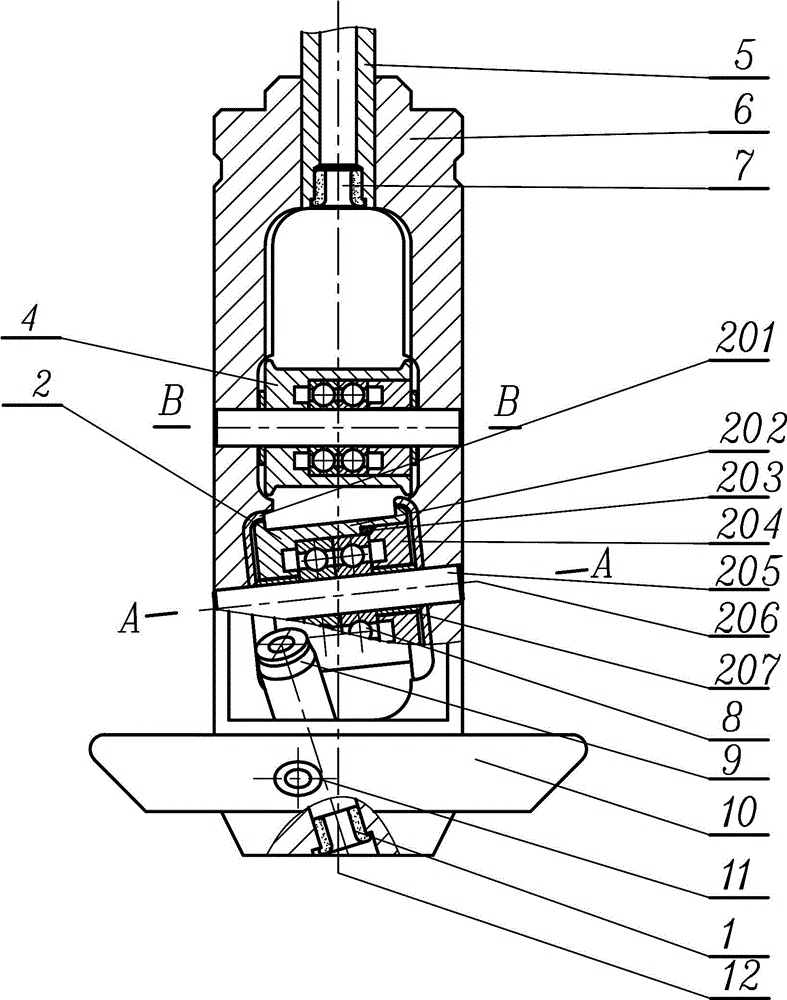
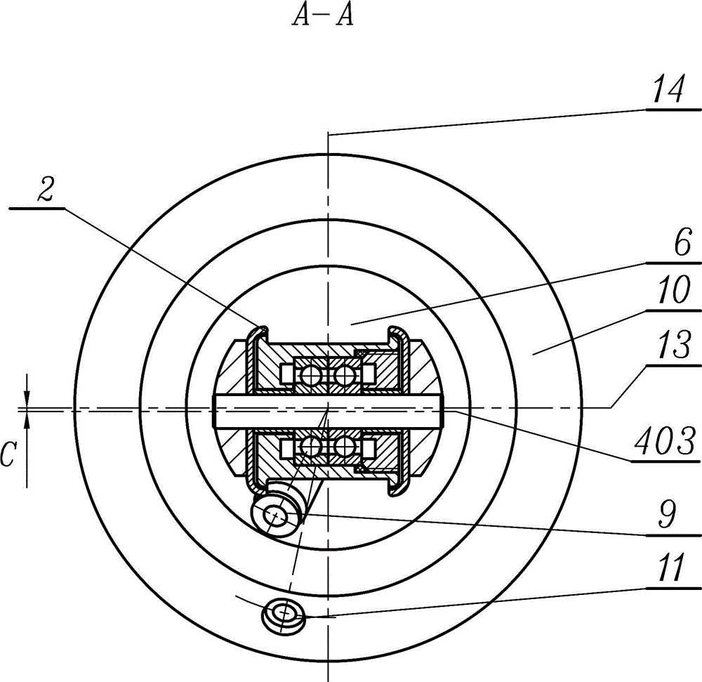
[0025] Such as Figure 1~4 Among them, a twister rotor mechanism, the upper part of the rotor frame 6 is fixedly connected with the yarn guide tube 5, the lower part of the rotor frame 6 is fixedly connected with the balance disc 10, the first ceramic ring 11 is arranged on the balance disc 10, and the rotor frame 6 is provided with a second ceramic ring 9 , the bottom end of the rotor frame 6 is provided with a third ceramic ring 1 , and a first roller 2 and a second roller 4 are provided near the lower part of the hollow part of the rotor frame 6 . With this structure, the unequal tension difference between the inner and outer yarns with fluctuating tension can be reduced and evened before the plying, so that the unequal length difference between the inner and outer yarns after plying can be reduced.

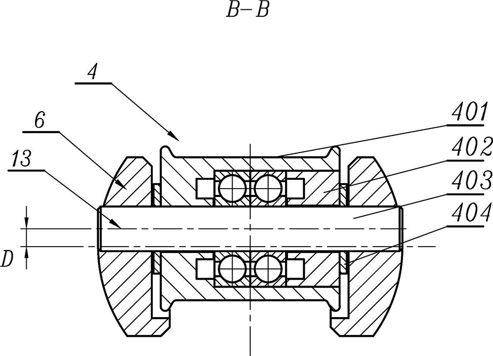
[0026] The preferred solution is as Figure 1~4 Among them, the first roller 2 is located below the second roller 4 , and the diameter of the first roller 2 is larger than th...


PUM


Abstract

The invention discloses a rotor mechanism of a twister. The upper part of a rotor frame is fixedly connected with a guide chase tube. The lower part of the rotor frame is fixedly connected with a balance disk. The balance disk is provided with a first porcelain ring and the rotor frame is internally provided with a second porcelain ring. The bottom end surface of the rotor frame is provided with a third porcelain ring. A first roller and a second roller are arranged at the hollow part of the rotor frame and are positioned closer to the lower part of the rotor frame. The first roller is positioned below the second roller. The diameter of the first roller is larger than the diameter of the second roller. The axis of the first roller is at an included angle relative to the horizontal plane. According to the technical scheme of the rotor mechanism of the twister, based on a built-in double-roller structure, the inner and outer yarns of two strands of tension fluctuation are wound onto the built-in double-roller structure for multiple cycles, so that the unequal-length difference between the tensions of inner and outer yarns is minimized and unified before the twisting process. Therefore, after the stranding process, the unequal-length difference between inner and outer yarns becomes smaller.

Description

technical field [0001] The invention relates to the field of twisters in textile machinery, in particular to a twister rotor mechanism. Background technique [0002] There is an existing twister with a twisting rotor for twisting. The publication number of the patent document is CN100552108C. The disk is fixedly connected, the axis of the yarn guide tube is coaxial with the balance disk, and the ceramic ring is set on the balance disk. A ceramic ring and a rotating combined roller are installed near the lower part of the gap in the middle of the rotor frame, and a ceramic ring is arranged on the end face. The combination roller is supported by a shaft installed in the rotor frame, and its axis is perpendicular to and intersects with the axis of the yarn guide tube, and the roller rotates around the shaft. The upper part of the rotor frame is connected with the yarn guiding tube, and the twisting rotor mechanism can flexibly rotate around the central axis of the rotor seat,...

Claims


Application Information

Patent Timeline
Patent Type & Authority Applications(China)
IPC IPC(8): D01H7/04D01H13/10
Inventor 陆国兴吕昌法汪斌
Owner YICHANG JINGWEI TEXTILE MACHINERY
Why Eureka
Try Eureka