
Lift gate device

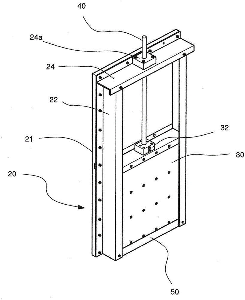
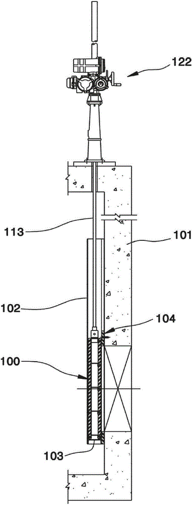
A lifting and gate technology, which is applied in water conservancy projects, sea area engineering, coastline protection, etc., can solve problems such as water stop damage, achieve the effects of preventing water stop damage, reducing usage, and reducing weight

Inactive Publication Date: 2016-01-27
KUM KANG IND CO LTD
View PDF6 Cites 1 Cited by
  • Summary
  • Abstract
  • Description
  • Claims
  • Application Information

AI Technical Summary

Problems solved by technology

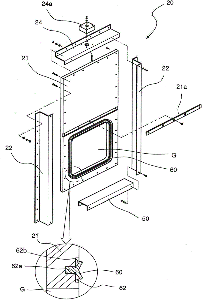
Accordingly, when the gate leaf (30) is lowered in order to close the gate, the lower end of the rear door leaf plate and the water stop (60) interfere with each other, causing early damage to the water stop (60)

Method used


Image

  • Lift gate device
  • Lift gate device
  • Lift gate device

Examples


Embodiment Construction

[0033] In the following detailed description, reference is made to the drawings to illustrate specific embodiments in which the present invention can be implemented.

[0034] These embodiments can give a full detailed description of the implementation of the present invention for those familiar with the technical scope. Even though the present invention is different from various embodiments, they are not necessarily mutually exclusive and incompatible. For example, when a certain embodiment does not deviate from the specific phenomenon, structure, or characteristic described in the present invention, it can be implemented in accordance with other embodiments.

[0035] In addition, the position or layout of individual elements in each disclosed embodiment can be modified without departing from the scope and spirit of the present invention. Therefore, the following description is not intended to limit its scope, but to appropriately illustrate the scope of the present invention, the...


PUM


Abstract

The present invention provides a lift gate device with the advantages of minimum consumption of gate frame plate material, portability, reduced cost, capacity of preventing water leakage caused by damage to waterstop, and having a structure meeting the requirements of assembling and disassembling convenience of a gate device. For this reason, the lift gate device comprises: a gate frame plate which has the functions of rise-fall guide and supporting for a gate leaf and consists of a gate intercept plate and left and right back guide plate components, wherein the gate intercept plate has a discharge hole for discharging stored water to the downstream position when the gate leaf is opened, and the left and right back guide plate components are configured at two sides of the upper part of the gate intercept plate in the form of upwards extending in a 11 shape at a certain interval; a waterstop arranged around the discharge hole of the gate intercept plate; left and right side gate slot components which are vertically fixed at the left and right sides of the gate frame plate and made of a steel material; L-shaped lock components arranged at the tops of the left and right side gate slot components for preventing rising of the gate leaf; the gate leaf vertically inserted between the left and right side gate slot components for opening and closing the gate fram plate; and a gate bottom support plate horizontally arranged at the bottoms of the left and right side gate slot components.

Description

Technical field [0001] The invention relates to a lift gate used for drainage, which minimizes materials used, prevents damage to the water stop, and has a structure that meets the convenience of assembly, installation and disassembly of gate devices. Background technique [0002] Generally, in places such as river dams or reservoirs, concrete dikes are set up to intercept a certain amount of water in the waterway to store a certain amount of water. In order to ensure a certain amount of water storage for agricultural or industrial water use, proper drainage is performed during the rainy season to prevent Flood gates were set up at these dams. [0003] This kind of gate includes a revolving gate that opens and closes the gate by means of a revolving gate, and a lift gate that lifts the gate to the upper opening gate. [0004] Revolving gates need to rotate heavy gates, especially in the case of high water pressure. Revolving gates have many difficulties, so they are often installed ...

Claims


Application Information

Patent Timeline
Patent Type & Authority Applications(China)
IPC IPC(8): E02B7/28E02B7/34E02B7/54
CPCE02B7/20
Inventor 黄富会黄铉轸
Owner KUM KANG IND CO LTD
Learn More