
Pressure lubrication system for free piston internal combustion engine generator

A technology for internal combustion generators and lubrication systems, applied in free piston engines, engine lubrication, pressure lubrication of lubrication pumps, etc., to achieve high volume power, compact structure, and avoid severe wear of parts

Active Publication Date: 2016-01-27
BEIJING INSTITUTE OF TECHNOLOGYGY
View PDF5 Cites 6 Cited by
  • Summary
  • Abstract
  • Description
  • Claims
  • Application Information

AI Technical Summary

Benefits of technology

This patented technology allows for better maintenance without causing damage or wearing away any part due to rubbing between moving components during operation. It uses an external hydraulic circuit instead of relying on gravity force from outside sources like springs or compressed air. By continuously supplementing lubricant into these circuits, it can maintain stable performance even at extreme temperatures over time.

Problems solved by technology

The technical problem addressed in this patents relates to improving the performance and efficiency of conventional internal combussion generators without causing excessive wear or damage due to their lack of a separate lubricant storage tank that can accommodate different types of lubricants such as water and gearboxes.

Method used


Image

  • Pressure lubrication system for free piston internal combustion engine generator
  • Pressure lubrication system for free piston internal combustion engine generator
  • Pressure lubrication system for free piston internal combustion engine generator

Examples

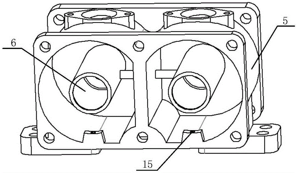
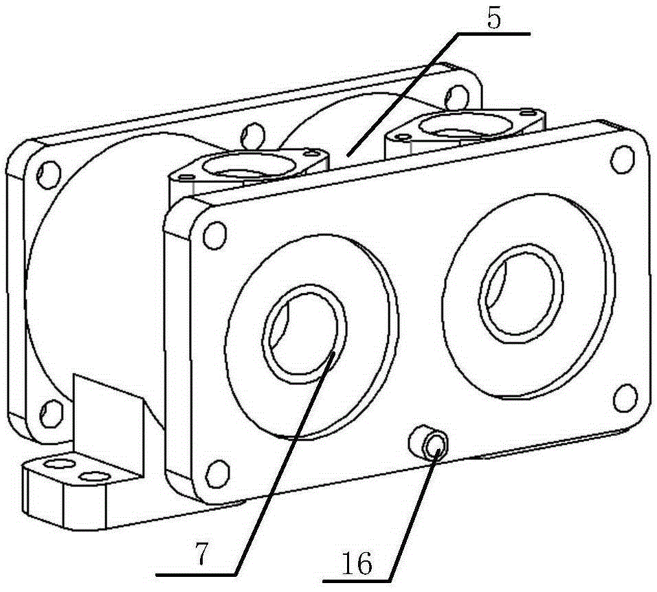

Embodiment 1

[0027] A pressure lubrication system for a free-piston internal combustion generator, such as figure 1 As shown, it mainly includes a free piston generator module, an oil tank 10 , an electric motor oil pump 11 , an oil filter 12 , an oil pipe 13 and a sealing ring 7 .

[0028] The free piston generator module mainly includes: cylinder 1, piston 2, connecting rod 3, cylinder liner 4, scavenging air box 5, linear motor stator coil 8 and motor mover 9.

[0029] like figure 2 , image 3 As shown, a lubricating oil chamber 6 is placed at the inner center of the scavenging box 5; the lubricating oil chamber 6 is a hollow cylinder, and the connecting rod 3 and the motor mover 9 reciprocate in the lubricating oil chamber 6; the lubricating oil chamber 6 and the sweeping The side of the air box 5 close to the stator coil 8 of the linear motor is fixedly connected, and a sealing ring 7 is arranged at the connection. The sealing ring 7 scrapes off the lubricating oil attached to the ...


PUM


Abstract

The invention relates to a pressure lubrication system for a free piston internal combustion engine generator and belongs to the field of energy power. The pressure lubrication system is characterized in that machine oil in a machine oil tank is pumped out through a machine oil pump, and divided into two branches after being filtered by a machine oil filter, then enters lubricating oil cavities and gaps between the lubricating oil cavities and a connecting rod rotor from first oil inlets and oil conveying pipelines of scavenging air receivers on the two sides, further enters an oil channel in a piston rod connecting rod assembly, and finally flows into a piston-air cylinder sleeve friction pair through oil outlets of the oil channel, so as to realize continuous lubrication of the lubrication surface. The system adopts a pressure lubrication mode, and does not have a coupling relationship with a motion process of the free piston generator, thereby being reliable in working and high in adaptability; the electric machine oil pump is adopted, so that accurate electronic control can be carried out conveniently according to different working conditions of an engine; and the lubricating oil cavities and the lubricating oil channel are arranged in a free piston generator module, so that the structure is compact, the space is saved and the relatively high volume power can be realized easily.

Description


Claims


Application Information

Patent Timeline
Owner BEIJING INSTITUTE OF TECHNOLOGYGY
Learn More