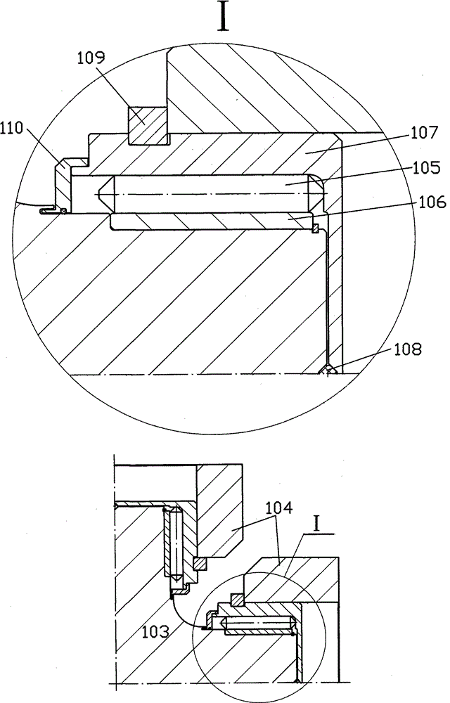
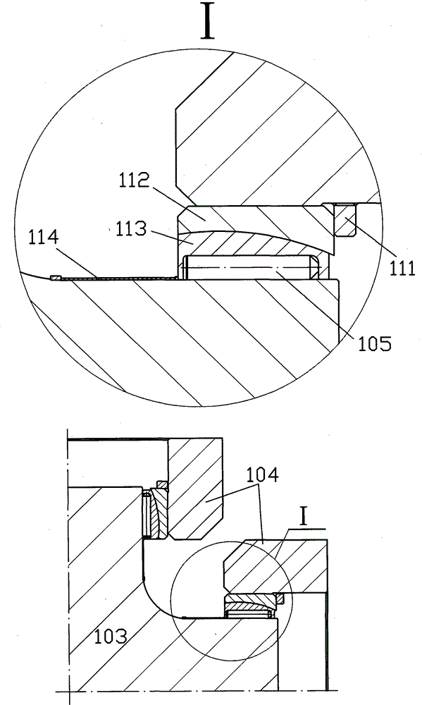
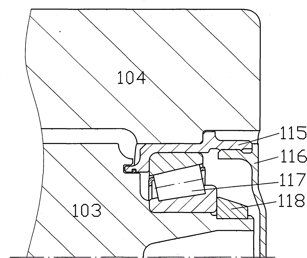
Suspended flexible flywheel

A technology of energy storage flywheel and flywheel device, which is applied in the direction of flywheel, etc., and can solve the problems of deformation change, unfavorable high-speed dynamic balance correction, creep deformation, etc.

Inactive Publication Date: 2016-01-27
徐立民
View PDF6 Cites 2 Cited by
  • Summary
  • Abstract
  • Description
  • Claims
  • Application Information

AI Technical Summary

Problems solved by technology

However, it is difficult to control the dynamic unbalanced force and moment of the composite wheel body with large mass and high linear speed
First of all, dynamic balance correction is difficult. First, a dynamic balancing machine with a large load is required; second, the combination of the wheel body and the rotating shaft is mostly a simply supported flexible rotor, which requires high-speed dynamic balance that is difficult to correct, and requires vacuum dynamic balance. Third, the fiber reinforced plastics under high-speed rotation will undergo large displacement and deformation, and the deformation will change with the speed, which is very unfavorable for high-speed dynamic balance correction
What is more unfavorable is the growth of dynamic imbalance during work. First, large displacement deformation occurs, and the difference in size and material makes this deformation uneven and symmetrical; second, gradual creep deformation occurs after long-term use.
The elastic deformation and creep of glass fiber reinforced plastics are large, while that of carbon fiber reinforced plastics is small, but the price and cost of materials with high elastic modulus such as carbon fiber are too high, which hinders large-scale economic application, while glass fiber is suitable for practical use. application, but to overcome the problem of large deformation and creep
[0004] In short, the rotation imbalance of the existing energy storage flywheel is large, difficult to solve the process, easy to cause large unbalance vibration, and the imbalance will be aggravated with the prolongation of use time
Also, most flywheels cannot avoid resonance speed in their operating speed range, causing the problem of passing the resonance point

Method used


Image

  • Suspended flexible flywheel
  • Suspended flexible flywheel
  • Suspended flexible flywheel

Examples


Embodiment Construction

[0060] A specific implementation of a suspended flexible flywheel device for power grid peak regulation (Fig. 23) is as follows.

[0061] Main parameters: rated speed 1321.9r / min, rated transmission power 12.8MW, maximum transmission torque 277398Nm (at 1 / 3 rated speed and above, rated power 12.8MW can be transmitted), maximum outer diameter of flywheel 9648mm, maximum outer diameter of device 10697mm, the total height of the device is 15894mm, the total weight of the device is 1414587kg, the total weight of the rotor is 1181437kg, and the rated energy storage is 38465kWh.

[0062] The flywheel rotor has 15 sets of wheel bodies arranged in series up and down, and each set of wheel bodies has two mass blocks (53) and two supporting bodies (54) ( Figure 18 ), each set of wheel body is connected with a cylindrical central shaft (102), the upper and lower adjacent central shafts are connected by flanges and threaded fasteners, the 14 central shafts located below have the same str...


PUM


Abstract

The invention provides a vertical energy storage flywheel device which is suitable for fixed places of power grid peak adjustment, wind power generation, uninterrupted power source, etc. Pulling-bearing twisting-transmitting flexible transmission members of circular chain, universal drive shaft or wire rope, etc. are used for suspending the flywheel body below a rotating shaft. The flywheel is provided with one or more sets of serially connected wheels. Each set of wheels is provided with one or more mass blocks and one or more supporting members which are connected through a flexible film ring and a bearing end surface pair. The rotating shaft is provided with a set of axial supporting permanent magnetic bearings. Two ends of the rotating shaft can be provided with radial rolling bearings or radial magnetic suspension bearing. A rotating member is arranged in a vacuum container. The suspended structure of the wheel can settle problems of unbalance and resonance in a conventionally used simple supported rotor in which the wheels are combined with the rotating shaft. The plurality of sets of serially connected wheels facilitate manufacture and increase of energy storage volume density. A plurality of axial supporting permanent magnetic bearings in a line or a row settle a problem of supporting a large-mass flywheel.

Description

Technical field [0001] The invention relates to an energy storage flywheel device, in particular to an energy storage flywheel device applied in a fixed place. Background technique [0002] The energy storage flywheel uses the kinetic energy of the high-speed rotating wheel body to store mechanical energy, which can be used in occasions that require energy storage and conversion, including grid peak regulation, wind power generation, uninterruptible power supply and other fixed places. [0003] The kinetic energy of the flywheel comes from the fact that the larger mass of the flywheel rotates at a high linear speed, and the quality blocks of the wheel body are all wound with unidirectional continuous fiber-reinforced plastic composite materials to obtain the maximum energy storage density by utilizing the high-strength characteristics of fiber-reinforced plastics . However, it is difficult to control the dynamic unbalanced force and moment of the composite wheel body with l...

Claims


Application Information

Patent Timeline
IPC IPC(8): F16F15/30
CPCY02E60/16
Inventor 徐立民
Owner 徐立民
Why Eureka
Try Eureka