
Self-opening vacuum circuit breaker device

A vacuum circuit breaker, self-opening and closing technology, applied in the direction of high-voltage air circuit breakers, circuits, electric switches, etc., can solve problems such as accident-prone, easy-to-failure, complex structures, etc., to simplify the mechanical pull drive system and avoid opening Combined resistance, simple and compact structure

Active Publication Date: 2017-11-10
杨斌堂
View PDF5 Cites 0 Cited by
  • Summary
  • Abstract
  • Description
  • Claims
  • Application Information

AI Technical Summary

Problems solved by technology

[0003] Existing vacuum circuit breakers usually use an external mechanical opening and closing control mechanism for opening and closing control; however, the existing mechanical opening and closing mechanism system usually has a very complicated structure, which is inconvenient to install and prone to failure, resulting in vacuum Circuit breaker opening and closing failures are prone to accidents, and the reliability of vacuum circuit breakers cannot be guaranteed
[0004] At present, there is no description or report of the similar technology of the present invention, and no similar data at home and abroad have been collected yet.

Method used


Image

  • Self-opening vacuum circuit breaker device
  • Self-opening vacuum circuit breaker device
  • Self-opening vacuum circuit breaker device

Examples


Embodiment 1

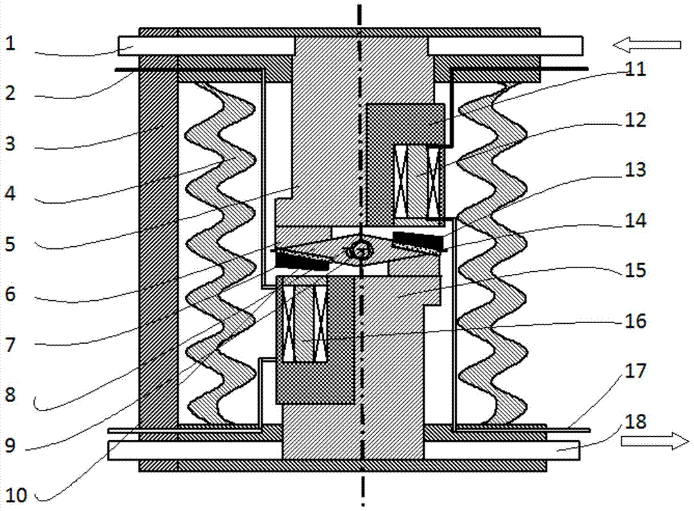
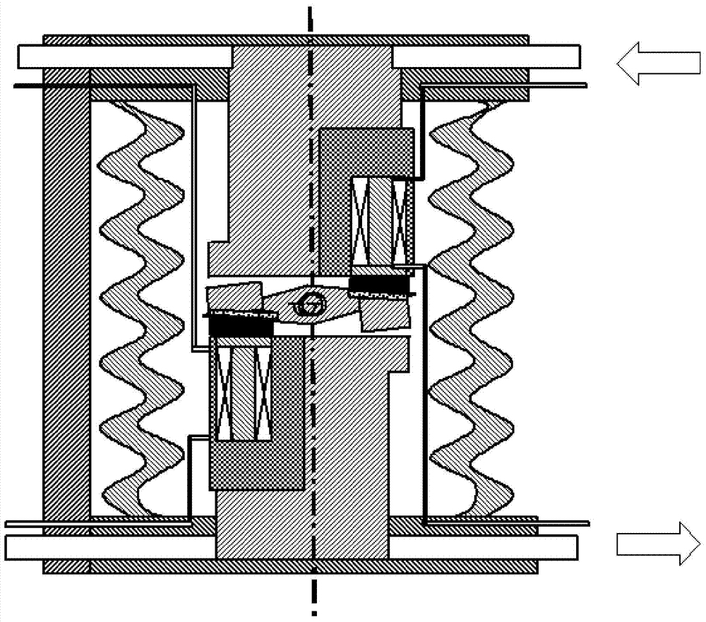
[0076] Such as figure 1 As shown, this embodiment provides a self-opening and closing vacuum circuit breaker device, including a main current input electrode 1, an excitation current input electrode 2, a vacuum chamber, an upper electrode column 5, a lower electrode column 15, an excitation current output electrode 17, The main current output electrode 18 and the opening and closing control mechanism; wherein:

[0077] The opening and closing control mechanism includes an opening and closing mechanism and a control mechanism, the opening and closing mechanism is arranged between the upper electrode column 5 and the lower electrode column 15, and a control magnetic field is formed between the control mechanism and the opening and closing mechanism; the main The current input electrode 1 is connected to the outer end of the upper electrode column 5; the main current output electrode 18 is connected to the outer end of the lower electrode column 15; the excitation current input e...

Embodiment 2

[0102] Embodiment 2 is a modification example of Embodiment 1.

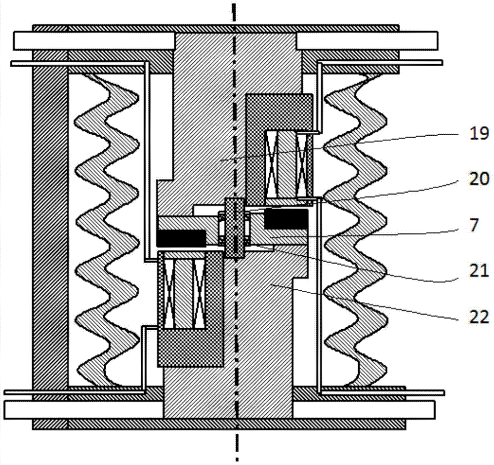
[0103] Such as image 3 As shown, the difference between embodiment 2 and embodiment 1 is:

[0104] The lower edge of the upper electrode column 5 is provided with an upper salient pole column 19;

[0105] The upper edge of the lower electrode column 15 is provided with a lower salient electrode column 22;

[0106] The opening and closing mechanism includes a rotating structure body 7, a first magnetic body and a second magnetic body. The rotating structure body 7 is a planar conductor structure, and a non-conductive rotating shaft 20 is provided at the center of the rotating structure body 7. The axis of the conductive rotating shaft 20 coincides with the axis of the upper electrode column 5 and the lower electrode. The rotating structure 7 can rotate around the non-conductive rotating shaft 20 between the upper electrode column 5 and the lower electrode column 15. The first magnetic body and the The second m...

Embodiment 3

[0111] Embodiment 3 is a modification example of Embodiment 1.

[0112] Such as Figure 5 As shown, the difference between embodiment 3 and embodiment 1 is:

[0113] The opening and closing mechanism includes a rotating sphere 24 with at least one magnetic body built in, and the rotating sphere 24 includes a rigidly spliced ​​non-conductive structure 24022401 and a conductive structure 2402;

[0114] The control mechanism includes two electromagnetic coils (an upper large coil 23 and a lower large coil 25 ), and the two electromagnetic coils are respectively wound on the outside of the upper electrode column 5 and the lower electrode column 15 .

[0115] The working principle of this embodiment is:

[0116] The excitation current input electrode 2 inputs the excitation current to the electromagnetic coil, so that the electromagnetic coil generates an electromagnetic field, and forms a control magnetic field with the magnetic body built in the rotating sphere 24, and the magn...


PUM


Abstract

The invention provides a self-opening / closing vacuum breaker device. The device comprises a main current input electrode, an excitation current input electrode, a vacuum chamber, an upper electrode column, a lower electrode column, an excitation current output electrode, a main current output electrode and an opening / closing control mechanism. The opening / closing control mechanism comprises an opening / closing mechanism and a control mechanism. The opening / closing mechanism is arranged between the upper electrode column and the lower electrode column. A control magnetic field is formed between the control mechanism and the opening / closing mechanism. The main current input electrode is connected with an outer end of the upper electrode column, and the main current output electrode is connected with an outer end of the lower electrode column. The excitation current input electrode and the excitation current output electrode are connected with the control mechanism. An inner end of the upper electrode column, an inner end of the lower electrode column and at least the opening / closing mechanism of the opening / closing control mechanism are all arranged inside the vacuum chamber. The device completely removes a complex external mechanical opening / closing mechanism system of a breaker in the prior art, and is simple and compact in structure, high in system integrated level, and quick and sensitive for using.

Description

technical field [0001] The present invention relates to the technical field of vacuum circuit breakers, in particular to a self-opening and closing vacuum circuit breaker device. Background technique [0002] Vacuum circuit breakers have the advantages of small size, light weight, suitable for frequent operations, and no maintenance for arc extinguishing, and are widely used in distribution networks. Vacuum circuit breaker is an indoor power distribution device in 3-10kV, 50Hz three-phase AC system, which can be used for protection and control of electrical equipment in industrial and mining enterprises, power plants, and substations, especially suitable for oil-free, less In places where maintenance and frequent operations are used, circuit breakers can be configured in central cabinets, double-layer cabinets, and fixed cabinets to control and protect high-voltage electrical equipment. The working principle of the vacuum circuit breaker is: when the dynamic and static cont...

Claims


Application Information

Patent Timeline
Patent Type & Authority Patents(China)
IPC IPC(8): H01H33/666
CPCH01H33/6662
Inventor 杨斌堂
Owner 杨斌堂
Learn More