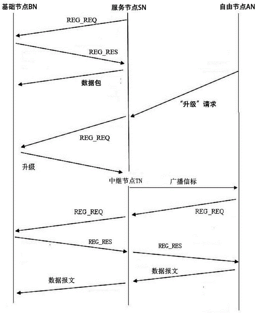
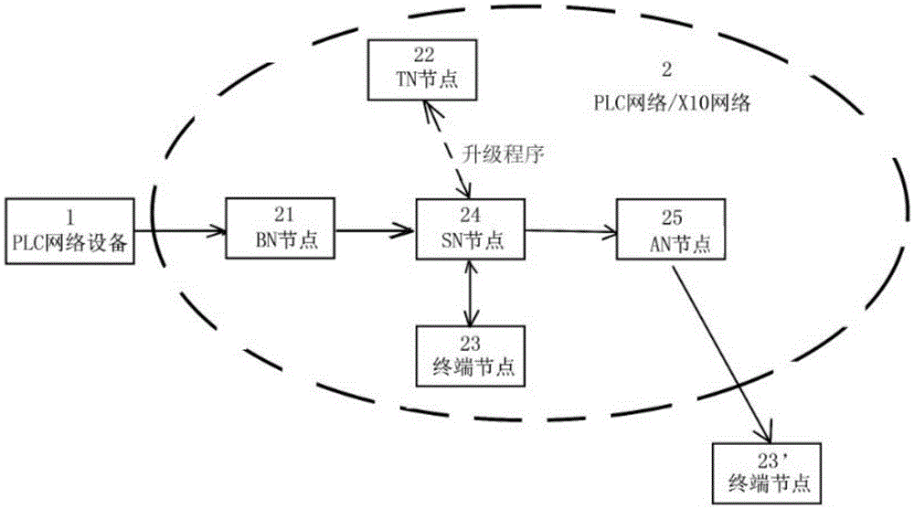
[0022] Example 1: Power Line Carrier Control (PLC) bus mode
[0023] The embodiment of the present invention abandons the use of RS485 bus or general R-type bus, that is, master-slave equipment must be used for communication, and a protocol mechanism is specified on the conventional PLC bus: indoor household electrical equipment, such as portable PCs, televisions or Electrical equipment such as smart refrigerators and air conditioners are used as free nodes AN. Users can start one of the electrical equipment, such as a TV, and send a "registration" request through the interactive interface of the TV itself to establish a local area data network. If there is a device responding to the request REG_REQ in an indoor space, such as a portable PC, then the PC will serve as the basic node BN at this time.
[0024] For example, in order to realize an effective connection between a smart TV and a PC, a handshake circuit or a computer program can be set respectively, so that the communication power between the two can be set at an appropriate value, that is, an effective connection can be established after the communication frequency matches. At this time, the PC is the only BN in the local area data network, and the smart TV is the service node SN. The smart TV is used to collect and acquire connection request information of other free nodes AN in the network. In a preferred example, the free node AN actively sends a "register" request to the bus.
[0025] It should be noted that when setting the service node SN and the basic node BN, the number of the basic node BN and the service node SN should be set to a certain ratio. All free nodes AN are set to "off" state. At this time, multiple free nodes AN are allowed to send "registration" request REG_REQ at the same time, and the number of other free nodes AN receiving this "registration" request REG_REQ command is limited by Restriction, that is, the ratio of the number of free nodes AN receiving "registration" information to the number of free nodes AN sending "registration" information is M.
[0026]This method can enable a plurality of electrical equipment with data sending and receiving capabilities to participate in the networking environment. Preferably, the free node AN that sends the "registration" information selects the free node AN that receives the "registration" information based on the communication intensity The strongest or the shortest distance between nodes is selected. The free node that sends the "registration" request and the basic node that receives the "registration" request are selected by the strongest communication strength or the shortest distance between nodes. The selection of the unique code address It can be a MAC address or a device name of an electrical device.
[0027] After the above actions are successfully completed, the basic node BN is set to be fixed, and the service node SN can be an active node, that is, the basic node BN cannot be changed or replaced, and the service node SN can be selected at will.
[0028] The format of the "data message" is composed of frame header, information body and filling bits. In general, even byte filling is designed. When the frame length is an odd number, the service node SN automatically fills an extra byte, such as 0X00 ; At the same time, before each data message is sent, the service node SN or any free node AN should send an identifying short transmission message to the basic node BN to identify whether the current electrical device is used as a free node AN or a service node Sn.
[0029] The content of the data message consists of:
[0030]
[0031] Preferably, the low-voltage PLC network adopts OFDM modulation, such as general narrow-band OFDM, based on PLC physical layer and MAC layer (i.e. MAC/PHY layer level, can be based on communication protocols such as IPv4 or IPv6 that may be used in the future, and the operating frequency is between 47.36~96.72KHz, the baud rate is 9600).
[0032] The above-mentioned free nodes AN also include some terminal nodes (23, 23'), these terminal nodes can be those nodes that cannot become the aforementioned SN/BN, or other free nodes AN outside the network 2, such as some Electrical equipment, switches, etc. that do not have computing power; or, these terminal nodes are nodes other than those selected as service nodes SN in multiple free nodes AN, and these nodes will not be used as service nodes SN to ensure that no As described above, on the one hand, the number of free nodes AN is limited, and on the other hand, request conflicts with other free nodes AN are avoided in the "upgrade" step.
[0033] As an improvement measure for this example, in order to avoid the signal conflict of the "registration" request, one or more of the service nodes SN that have been used as the relay node TN will be "downgraded" to the original service node SN and set to e.g. In the "non-conducting" state or "conducting" but not participating in the "registration" request action, considering the difference in the timing of data transmission, in order to reduce the possibility of signal conflicts, the basic node BN should be set to judge according to the timing , For example, in the "upgrade" step, the request may be received repeatedly or simultaneously, because when sending data packets, the nodes will not automatically detect whether there is a data sending and receiving conflict on the communication channel.
[0034] Another case of "degradation" is that some relay nodes TN will send at least one connection request ATTACH_REQ to the original basic node BN when there is a failure in data transmission and reception with the service node SN or terminal node, if the ATTACH_REQ After being received by other basic node BN, this basic node BN can be set to "normal conduction" state.
[0035] like figure 2 As shown, PLC network device 1 can be used as a backbone network, and PLC network 2 can be used as its sub-network. The types of networks 1 and 2 can be different, because electrical equipment does not need to know the current network status and configuration. The network system 2 is mainly composed of multiple free nodes AN. AN is a variety of electrical equipment with data sending and receiving functions in the user's home, and AN is divided into BN node 21 and SN node 24, or AN node 25, wherein BN node 21 Once generated, it becomes a fixed transceiver. As an improvement of this kind of network, according to the aforementioned principle, the "registration" request REG_REQ is used as an "identifying short delivery message". This improvement can overcome:
[0036] 1. If the protocol of network 1 and sub-network 2, or the network protocols of sub-network 2 and terminal node 23' cannot coexist, due to the different protocol structures, they cannot actively identify each other's data transmission, or there will be conflicts in order to avoid network conflicts. Without identification, this situation involves each network using its own independent digital identifier (such as a digital signature or serial number) to indicate whether the same channel is in a "free" or "occupied" state. One embodiment is to use the TOKEN code. An encrypted frame structure, according to the characteristics of the TOKEN code to identify whether the "registered" electrical equipment on the network is in the "occupied" state;
[0037] 2. The signal transmission power between network 1 and network 2 and the network where the terminal node 23' is located may be different. For example, the aforementioned low-voltage PLC carrier mode is used, and a higher medium-voltage carrier is required on some specific devices, but this This kind of problem also needs to design the number of turns of the coil of the transmitter to avoid.
[0038] For this reason, before sending the data message, add the identification short transmission message to the electrical equipment where the BN node of different networks is located, for example, re-add part of the MTP content, and the modified electrical equipment where the terminal node 23' is located can be integrated into the network 2 message transmission. For example, the terminal node 23' is defined with a sampling frequency of 300Khz, then it can be modified to redefine sampling to 500KHz under the network 2 and continue to run with this clock, and the registered SN device 24 in the PLC network 2 will easily receive To the front identification short message from node 23', so as to identify the CRC-header for decoding, so that if the terminal node 23' is integrated into the network 2, the node 24 can receive its data message transmission, and can perform the aforementioned "upgrade"/downgrade steps.