Syringe driving mechanism and injection pump

A driving mechanism and syringe technology, which is applied in the field of syringe pumps, can solve problems such as screw rod and split nut damage, inability to engage the transmission, and syringe pumps cannot be used normally, so as to achieve easy adjustment operation, ensure safety, and ensure safety. Effect

Active Publication Date: 2016-02-03
深圳莫微医疗技术有限公司
View PDF7 Cites 10 Cited by
  • Summary
  • Abstract
  • Description
  • Claims
  • Application Information

AI Technical Summary

Problems solved by technology

In the above method, in the process of adjusting the position of the push head, it is necessary to hold the dial button all the time. It is very easy for the operator to not hold the dial button in place, resulting in the split nut not being completely disengaged from the screw rod. , that is, the thread crest of the split nut and the thread crest of the screw are still facing each other. At this time, moving the push head will cause the thread crest of the split nut and the thread crest of the screw to wear each other (that is, grinding teeth), resulting in the screw and the opening and closing The nut is damaged and cannot engage the drive, preventing the syringe pump from functioning properly

Method used


Image

  • Syringe driving mechanism and injection pump
  • Syringe driving mechanism and injection pump
  • Syringe driving mechanism and injection pump

Examples


Embodiment Construction

[0027] The following will clearly and completely describe the technical solutions in the embodiments of the present invention with reference to the accompanying drawings in the embodiments of the present invention. Obviously, the described embodiments are only part of the embodiments of the present invention, not all of them. Based on the embodiments of the present invention, all other embodiments obtained by persons of ordinary skill in the art without creative efforts fall within the protection scope of the present invention.

[0028] It should be noted that all directional indications (such as up, down, left, right, front, back...) in the embodiments of the present invention are only used to explain the relationship between the components in a certain posture (as shown in the accompanying drawings). Relative positional relationship, movement conditions, etc., if the specific posture changes, the directional indication will also change accordingly.

[0029] In addition, the ...


PUM


Abstract

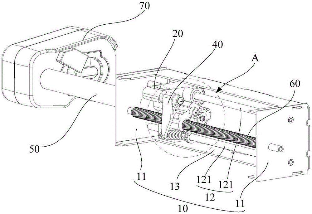
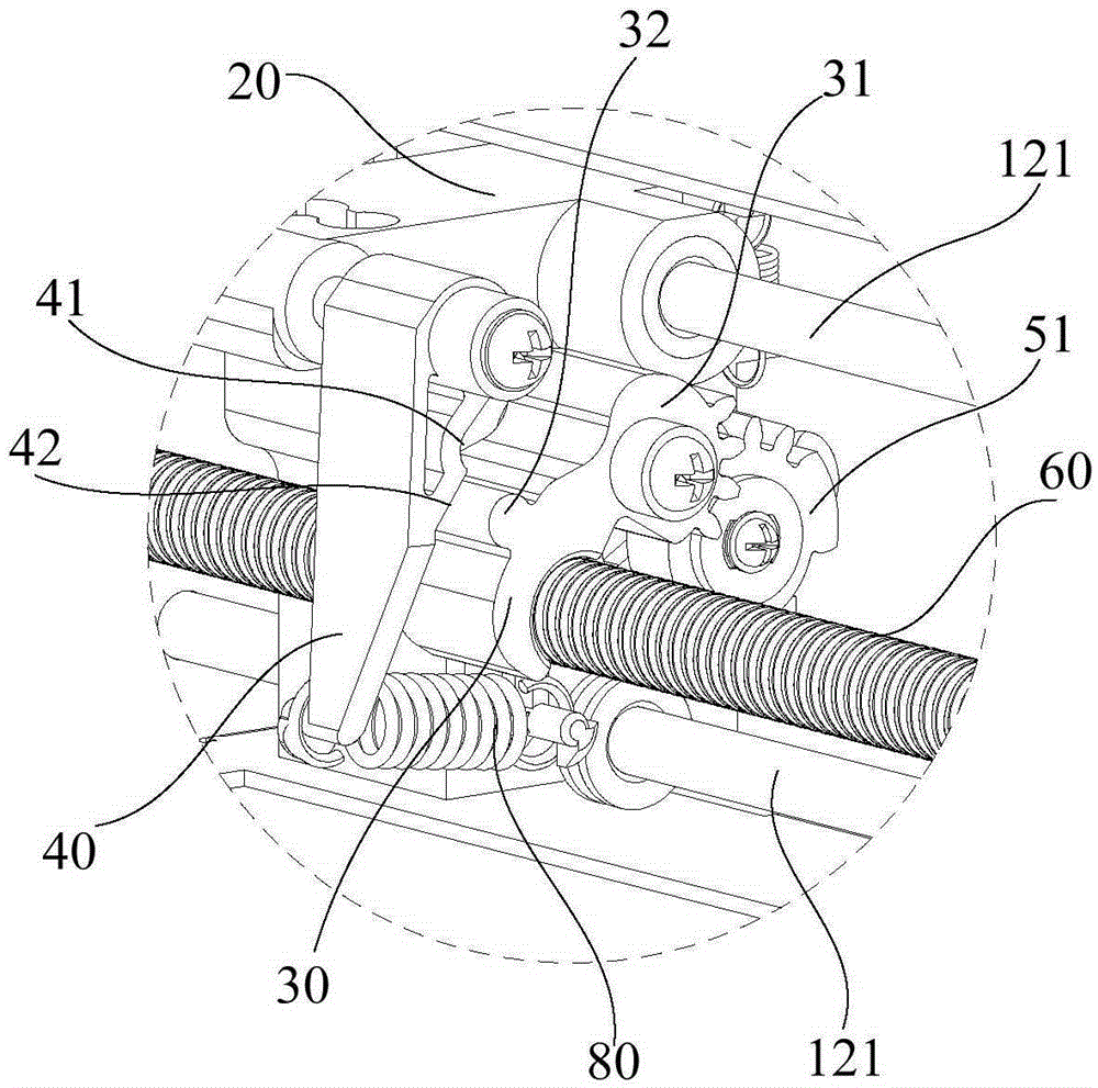
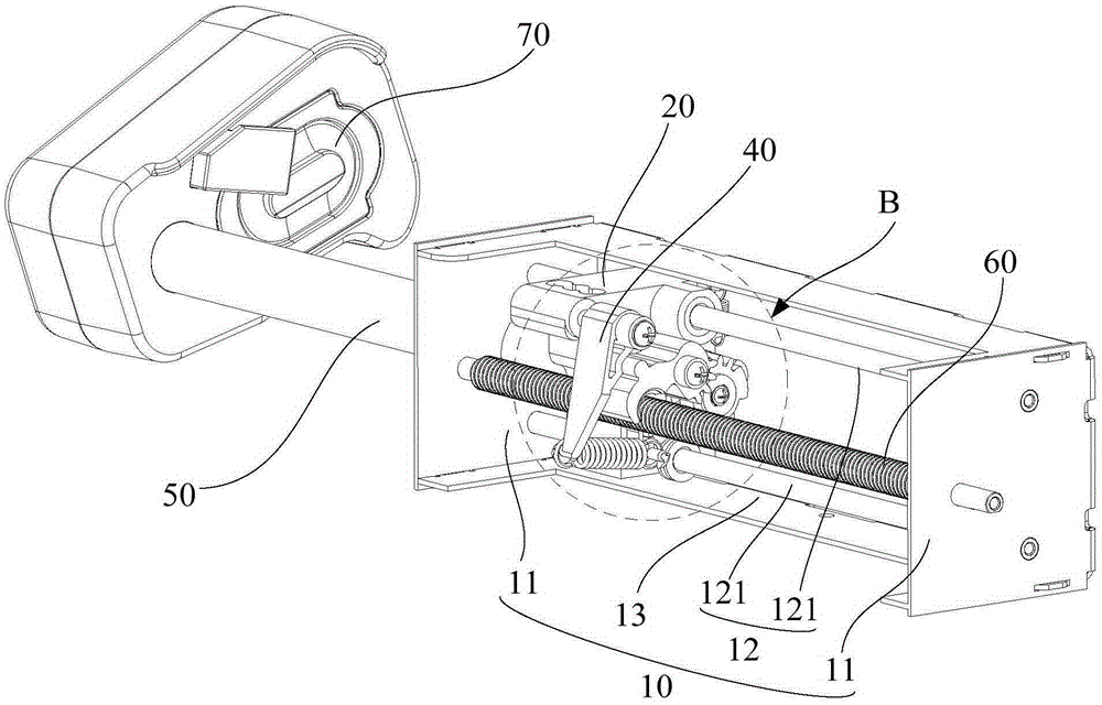
The invention discloses a syringe driving mechanism and an injection pump, wherein the syringe driving mechanism comprises a stand, a sliding base, a split nut, a press block, a push rod and a screw rod which is arranged in a mode of being parallel with the push rod; the stand comprises two end plates and a guide component; the split nut is meshed with the screw rod; a driven piece and a limiting part are arranged on the peripheral wall of the split nut; the driven piece is connected to the sliding base in a rotatable mode; a rotating shaft of the driven piece is parallel with the screw rod; the press block is connected to and arranged on the sliding base; the press block is elastically propped against the limiting part; a clamping part, which is clamped and matched with the limiting part, is arranged on the press block; the sliding base is movably sleeved on the push rod, and the push rod is capable of undergoing a spinning motion relative to the sliding base; a driving piece, which is transmitted and matched with the driven piece, is arranged on the push rod, and the driven piece is rotated by the driving piece when the push rod is rotated; and the split nut is completely separated from the screw rod when the limiting part is clamped into the clamping part. Through the technical scheme of the invention, a phenomenon that the split nut and the screw rod are ground in an operation of adjusting the position of a push head, so that the safety of the injection pump is guaranteed.

Description

technical field [0001] The invention relates to the technical field of syringe pumps, in particular to a syringe driving mechanism and a syringe pump. Background technique [0002] At present, the syringe pump usually engages with the screw rod through the split nut to drive the push head assembly through the screw rod. The push head assembly is mainly composed of a push rod connected with the split nut on the same sliding seat and a push rod connected The syringe is fixed on the frame, and the push head is connected to the tail of the piston rod of the syringe to push the piston rod to control the discharge of the syringe. Since the piston rods of different types of syringes have different lengths, when installing the syringe, it is usually necessary to adjust the distance between the push head and the syringe so that it is just connected to the tail of the piston rod of the syringe. [0003] The current method of adjusting the push head of the syringe pump is: the operato...

Claims


Application Information

Patent Timeline
Patent Type & Authority Applications(China)
IPC IPC(8): A61M5/20
Inventor 周杰王争梁祥锦易燕成
Owner 深圳莫微医疗技术有限公司
Why Eureka
Try Eureka