Self-locking type integrated lifting mechanism

A lifting mechanism and self-locking technology, applied in the field of integrated lifting mechanism, can solve the problems of structural redundancy, angle offset, low stability, etc., and achieve simple and reasonable structural design, increased bending moment resistance, and compact structure Effect

Active Publication Date: 2016-02-03
HARBIN INST OF TECH
View PDF6 Cites 1 Cited by
  • Summary
  • Abstract
  • Description
  • Claims
  • Application Information

AI Technical Summary

Problems solved by technology

[0003] The purpose of the present invention is to provide a self-locking integrated lifting mechanism to solve the problem that the existing lifting mechanism is prone to angle deviation and low stability during the position movement process. In addition, most lifting mechanisms require mechanical or electrical brakes. It brings additional design difficulties, and at the same time, most of the lifting mechanisms adopt linear drive mode, which requires a large volume and redundant structures

Method used


Image

  • Self-locking type integrated lifting mechanism
  • Self-locking type integrated lifting mechanism
  • Self-locking type integrated lifting mechanism

Examples


specific Embodiment approach 1

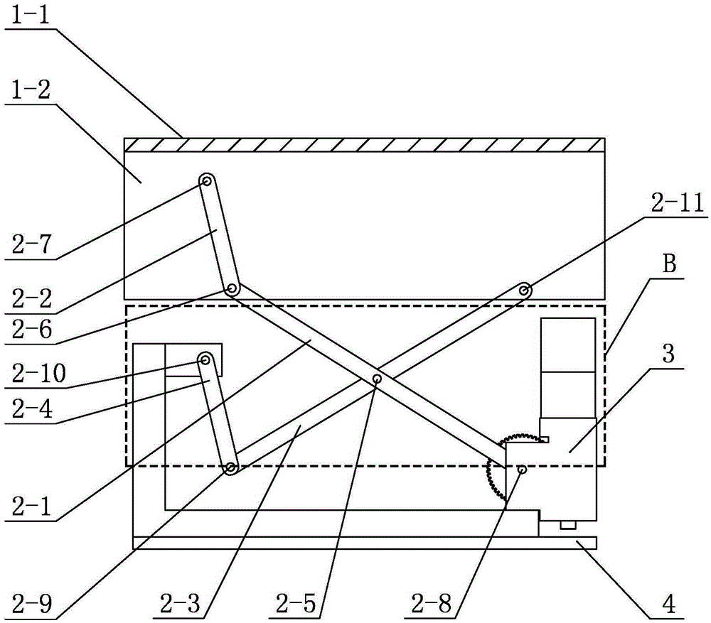
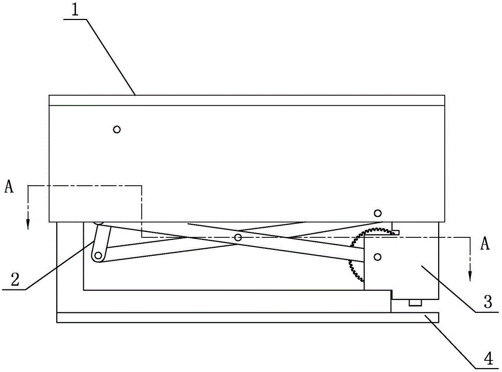
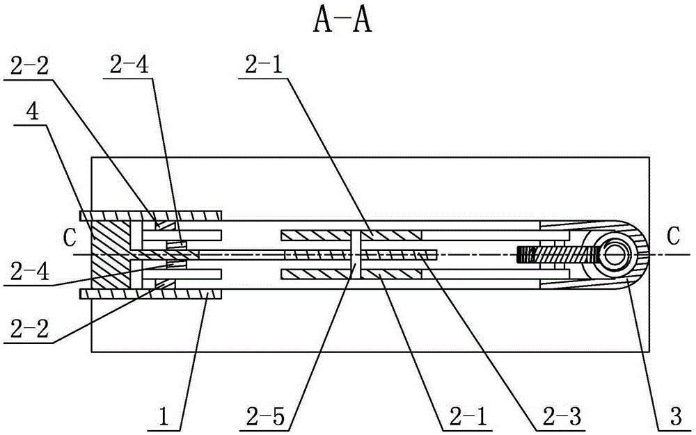
[0021] Specific implementation mode one: combine figure 1 , figure 2 , image 3 , Figure 4 , Figure 5 and Figure 6 Describe this embodiment. This embodiment includes a lifting platform 1, a connecting rod movement module 2, a driving module 3 and a fixed frame 4. The connecting rod moving module 2 is arranged on the fixing frame 4, and the lifting platform 1 is arranged on the connecting rod On the movement module 2, the drive module 3 is inlaid on the fixed frame 4 and connected with the link movement module 2;

[0022] The lifting platform 1 includes a top board 1-1 and two side boards 1-2, the top board 1-1 is arranged horizontally, and the two side boards 1-2 are arranged vertically and side by side under the top board 1-1;

[0023] The drive module 3 includes a drive motor 3-1, a worm screw 3-2 and a worm wheel 3-3, the output shaft of the drive motor 3-1 is connected to the worm screw 3-2, and the worm wheel 3-3 is connected to the worm screw 3-2. 2 meshing;

...

specific Embodiment approach 2

[0029] Specific implementation mode two: combination figure 1 , figure 2 and image 3 To illustrate this embodiment, the drive module 3 in this embodiment also includes a motor fixing seat 3-7, a coupling 3-8, a top bearing 3-4, a driving fixing seat 3-5, and a bottom bearing 3-6, The drive mount 3-5 is arranged vertically, and the shaft coupling 3-8, the top end bearing 3-4 and the bottom end bearing 3-6 are sequentially arranged on the drive mount 3-5 from top to bottom. The worm 3-2 is arranged between the top bearing 3-4 and the bottom bearing 3-6, the motor holder 3-7 is fixedly connected to the top of the drive holder 3-5, and the drive motor 3-1 is arranged on On the motor fixing seat 3-7, the output shaft of the driving motor 3-1 is connected with the worm screw 3-2 through a shaft coupling 3-8.

[0030] In the present invention, the mutual motion between the lifting platform 1, the first homologous output link 2-2 and the coupling link 2-3 is the first revolving p...

specific Embodiment approach 3

[0031] Specific implementation mode three: combination figure 1 , figure 2 , Figure 5 and Figure 6 Describe this embodiment, in this embodiment, the fixed frame 4 includes an L-shaped fixed plate 4-1, a connecting plate 4-2 for a link movement module and a bottom plate 4-3, the bottom plate 4-3 is horizontally arranged, and the The L-shaped fixed plate 4-1 is vertically arranged on the bottom plate 4-3, and the bottom of the drive fixed seat 3-5 is clamped on the horizontal end of the L-shaped fixed plate 4-1, and the L-shaped fixed plate 4- The vertical end of 1 is fixedly connected with the connecting plate 4-2 for the connecting rod movement module arranged horizontally, and the other end of each second homologous output connecting rod 2-4 is hinged on the connecting plate 4-2 for the connecting rod moving module. 2 on. The layout of the fixed frame 4 arranged in this way is reasonable, so that it takes up little space. Other structures and connections are the same ...


PUM


Abstract

The invention relates to a lifting mechanism, in particular to a self-locking type integrated lifting mechanism. The rotational movement of an existing lifting mechanism is limited through a guiding slide rail, and a large size and large friction force are caused; additional mechanical or electrical band-type brakes are needed, and the design difficulty is increased; a linear moving module is large in size and redundant in structure. According to the self-locking type integrated lifting mechanism, a connecting rod movement module is arranged on a fixing frame, a lifting platform is arranged on the connecting rod movement module, and a driving module is arranged on the fixing frame and connected with the connecting rod movement module. The middle of a driving connecting rod and the middle of a coupling connecting rod are hinged, one end of the driving connecting rod is hinged to one end of a first homologous output connecting rod, and the other end of the first homologous output connecting rod is hinged to the inner wall of a side plate. The other end of the driving connecting rod is fixedly connected with a worm gear. One end of the coupling connecting rod is hinged to one end of a second homologous output connecting rod, the other end of the second homologous output connecting rod is hinged to the fixing frame, and the other end of the coupling connecting rod is hinged to the inner wall of the corresponding side plate. The self-locking type integrated lifting mechanism is applied to lifting movement.

Description

technical field [0001] The invention relates to an integrated lifting mechanism, which belongs to the technical field of mechanical equipment. Background technique [0002] The lifting mechanism is widely used, mainly in industrial production. The lifting mechanism can quickly switch between different stations through a simple method. Most of the existing lifting mechanisms need guide rails to limit the rotational movement, which brings inconvenience in terms of structural volume and layout, and has a large impact on the gap and friction of the moving pair; in industrial operations Among them, stability is a necessary condition. Most of the existing lifting mechanisms require mechanical or electrical brakes, which brings additional design difficulties; most of the existing lifting mechanisms adopt linear drive mode, and the rotational motion of the motor is converted into the linear motion of the screw. Requires larger volume and redundant structure. These factors all limi...

Claims


Application Information

Patent Timeline
Patent Type & Authority Applications(China)
IPC IPC(8): B25H1/16
CPCB25H1/16
Inventor 樊绍巍吴军金明河
Owner HARBIN INST OF TECH
Why Eureka
Try Eureka