Mechanical arm working at multiple angles

Active Publication Date: 2016-02-03
广州东焊智能装备有限公司
View PDF8 Cites 11 Cited by
  • Summary
  • Abstract
  • Description
  • Claims
  • Application Information

AI Technical Summary

Problems solved by technology

[0004] Aiming at the deficiencies of the prior art, the present invention provides a multi-angle working mechanical arm, which overcomes the disadvantages of traditional hydraulic excavators such as high maintenance cost, high operating noise, high cost of hydraulic components, and insufficient sensitivity of response.

Method used


Image

  • Mechanical arm working at multiple angles

Examples


Embodiment 1

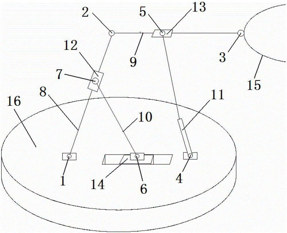
[0016] The multi-angle working mechanical arm includes rod one 8, rod two 9, rod three 10, telescopic rod 11, sliding sleeve one 12, sliding sleeve two 13, slider 14, actuator 15 and working platform 16,

[0017] The lower end of the rod one 8 is connected to the working platform 16 through the rotating pair one 1, the upper end of the rod one 8 is connected to one end of the rod two 9 through the rotating pair two 2, and the other end of the rod two 9 is connected to the actuator 15 through the rotating pair three 3,

[0018] The lower end of the telescopic rod 11 is connected to the working platform 16 through the rotating pair 4, and the upper end of the telescopic rod 11 is connected to the sliding sleeve 2 13 through the rotating pair 5, and the sliding sleeve 13 is sleeved on the rod 9.

[0019] The lower end of the rod three 10 is connected on the slide block 14 through the rotating pair six 6, and the slide block 14 is installed in the chute of the working platform 16, ...


PUM


Abstract

The invention discloses a mechanical arm working at multiple angles. The lower end of a first rod of the mechanical arm is connected to a work platform through a first rotation pair; the upper end of the first rod is connected with one end of a second rod through a second rotation pair; the other end of the second rod is connected to an executor through a third rotation pair; the lower end of a telescopic rod is connected to the work platform through a fourth rotation pair; the upper end of the telescopic rod is connected to a second slide sleeve through a fifth rotation pair; the second rod is sleeved with the second slide sleeve; the lower end of a third rod is connected to a slider through a sixth rotation pair; the slider is installed in a slide groove of the work platform; the upper end of the third rod is connected to a first slide sleeve through a rotating pair; the first rod is sleeved with the first slide sleeve; and the work platform is installed on a trolley through an eighth rotation pair. The number of driving rods and controllable motors is reduced while the mechanical arm working at multiple angles has the beneficial effects that a traditional hydraulic machine mechanism is large in work space and excavating force, good in stress and the like, and the complexity of a machine frame transmission system is reduced.

Description

technical field [0001] The invention relates to the mechanical field, in particular to a multi-angle working mechanical arm. Background technique [0002] Palletizing robots are widely used in automatic handling operations such as machine tool loading and unloading, stamping machine automated production lines, automatic assembly lines, palletizing, and containers. Existing palletizing robots mainly have three structural types: Cartesian coordinate type, cylindrical coordinate type and joint type. Among them, the articulated palletizing robot has gradually become the main structural form of the palletizing robot because of its compact structure, flexible movement, small footprint, and large working space. However, the drive motors of this type of palletizing robot with traditional open-chain series structure must be installed at the joints, resulting in problems such as heavy weight, poor rigidity, large inertia, and accumulated joint errors. The dynamic performance of the m...

Claims


Application Information

Patent Timeline
Patent Type & Authority Applications(China)
IPC IPC(8): B25J9/08B25J9/00B25J18/04
Inventor 覃煦
Owner 广州东焊智能装备有限公司
Why Eureka
Try Eureka