Manipulator for clamping dripping hopper component

A technology of manipulators and dropping funnels, applied in the direction of manipulators, chucks, catheters, etc., can solve problems such as inconvenient gripping, and achieve the effect of preventing upward movement from deviating from the position and ensuring stability

Active Publication Date: 2016-02-03
MAIDER MEDICAL IND EQUIP
View PDF9 Cites 1 Cited by
  • Summary
  • Abstract
  • Description
  • Claims
  • Application Information

AI Technical Summary

Problems solved by technology

[0004] The above-mentioned device includes a manipulator, which has only one clamping head, which is mainly used for clamping and transferring a single conduit, but for a whole dropping funnel assembly, it cannot be conveniently and accurately clamped

Method used


Image

  • Manipulator for clamping dripping hopper component
  • Manipulator for clamping dripping hopper component
  • Manipulator for clamping dripping hopper component

Examples


Embodiment 1

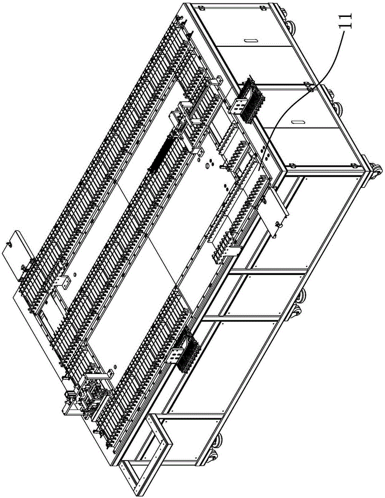
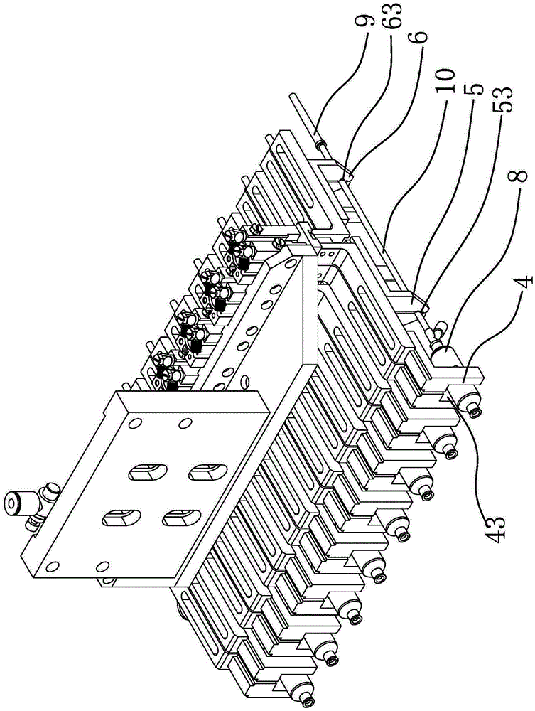
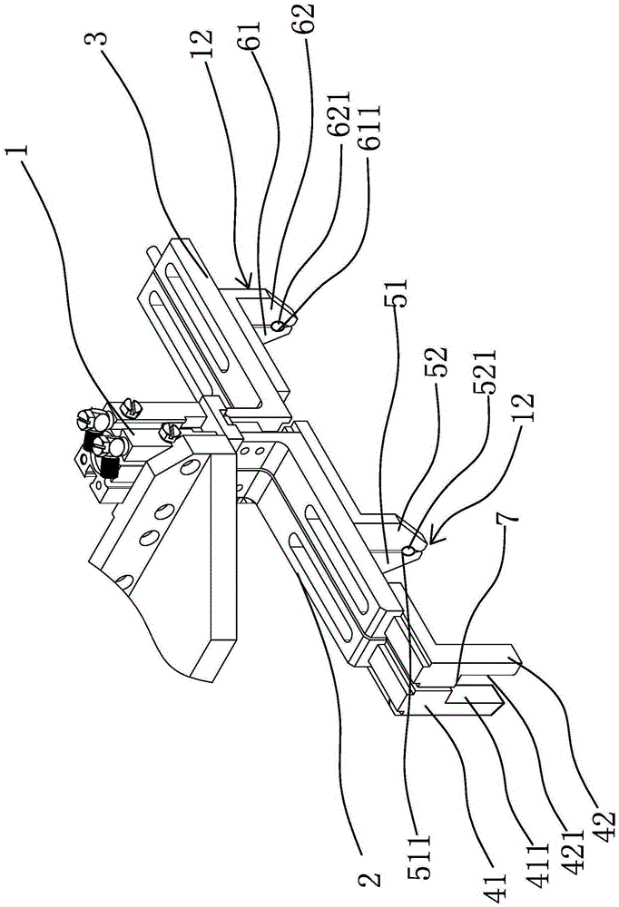
[0029] Such as Figure 1 to Figure 3 As shown, the manipulator in this embodiment includes a driver 1 and a drip funnel chuck 4 and a conduit chuck 12 that are connected to the driver 1 and arranged at intervals, and there are two conduit chucks 12, which are respectively conduit chuck-5 And conduit chuck two 6. The driver 1 can drive the chuck 4 of the dropping funnel, the first 5 of the conduit chuck 5 and the second 6 of the conduit chuck to be clamped or opened at the same time. The dripping funnel chuck 4 includes the first dripping funnel clamping arm 41 and the second dripping funnel clamping arm 42, and the first dripping funnel clamping arm 41 and the second dripping funnel clamping arm 42 can form a joint for clamping the dripping funnel 8 when they are clamped. The clamping mouth one 43; the conduit chuck one 5 includes the conduit clamping arm one 51 and the conduit clamping arm two 52 which are arranged oppositely, and the conduit clamping arm one 51 and the cond...

Embodiment 2

[0037] This embodiment is roughly the same as Embodiment 1, except that the limiting structure 7 in this embodiment is a protruding post, and the protruding post is arranged laterally on the side wall of the first 41 of the dripping funnel clamp arm and / or the second dripping funnel clamping arm. 42 on the side wall. Specifically, the protruding post can be horizontally arranged on the side wall of the dripping funnel clamp arm one 41; it can also be horizontally set on the side wall of the dripping bucket clamp arm two 42; The protrusions are arranged on the side wall and the side wall of the second clamp arm 42 of the dropping funnel, and the two protrusions are directly opposite to each other. In this embodiment, any one of the above three methods can be used to realize the position-limiting function.

[0038] In other embodiments, there may be one or more than two conduit clamps, such as three, four, etc., the number and position of which may be selected and set according ...


PUM


Abstract

The invention provides a manipulator for clamping a dripping hopper component, belongs to the technical field of manufacturing equipment of medical instruments, and solves such technical problems as weak stability of a traditional manipulator for clamping the dripping hopper component. The manipulator comprises a driving piece, wherein the driving piece is connected with a dripping hopper chuck and at least one guide pipe chuck capable of clamping a guide pipe; the dripping hopper chuck and the guide pipe chucks are spaced in sequence in a linear direction; the driving piece can drive the dripping hopper chuck and the guide pipe chucks to synchronously clamp or open; the dripping hopper chuck comprises a dripping hopper clamping arm 1 and a dripping hopper clamping arm 2 arranged oppositely; the dripping hopper clamping arm 1 and the dripping hopper clamping arm 2 are clamped to form a clamping port 1 for clamping a dripping hopper; the clamping port 1 has a downward opening; and a limiting structure capable of limiting upward movement of the dripping hopper is arranged in the clamping port 1. The manipulator clamps the dripping hopper component through three clamping points of the clamping port 1, a clamping port 2 and a clamping port 3 in a segmented manner, so that the dripping hopper component clamping stability of the manipulator is guaranteed.

Description

technical field [0001] The invention belongs to the technical field of manufacturing equipment of medical instruments, and relates to a production and assembly device for an infusion set catheter, in particular to a manipulator for gripping a dripping funnel assembly. Background technique [0002] The infusion set is an auxiliary device commonly used in medical treatment, mainly used for intravenous infusion. It is an important disposable medical consumable that has undergone aseptic treatment and establishes a channel between the vein and the liquid medicine. It is generally composed of an intravenous needle, a protective cap, a liquid medicine filter, a regulator for controlling the flow rate of the liquid medicine, a drip funnel assembly, and an air filter connection of the air intake pipe. All components are connected through conduits, and the medicinal liquid flows through the conduits. The dropping funnel assembly has the effect of buffering the liquid medicine, and c...

Claims


Application Information

Patent Timeline
IPC IPC(8): B25J15/00A61M25/16
Inventor 林军华
Owner MAIDER MEDICAL IND EQUIP
Why Eureka
Try Eureka