Clamping device for electrical equipment overhauling and installing

A technology of clamping device and electric equipment, applied in the direction of overhead line/cable equipment, chuck, manipulator, etc., can solve the problems of improving the safety of electric maintenance and installation, hidden danger, small opening and closing angle of the clamping part, etc., to reduce labor Strength, reducing safety hazards, and the effect of large opening and closing angles

Inactive Publication Date: 2016-02-03
常州亚各来德机电设备制造有限公司
View PDF1 Cites 16 Cited by
  • Summary
  • Abstract
  • Description
  • Claims
  • Application Information

AI Technical Summary

Problems solved by technology

In the process of overhauling and installing electrical equipment, workers often need to carry necessary tools or other devices to work at heights, which is very inconvenient to carry and also poses a great safety hazard
[0003] The clamping device for the maintenance and installation of electric equipment disclosed in the Chinese invention patent application publication CN204019400U, when the device is working in the hydraulic cylinder, drives the push rod to move back and forth, thereby driving the V-shaped connecting rod to move back and forth, further driving Therefore, the final effect is to expand or reduce the space enclosed by the upper clamping part and the lower clamping part of the clamping device, thereby realizing the loosening or Clamping, but because the upper clamping part and the lower clamping part are single-layer circular structures, the opening and closing angle of the clamping part is small, and it is easier to clamp objects, and the V-shaped connecting rod and the upper clamping part The central connection piece and the related adjustment parts between the clamping part and the lower clamping part make it impossible for the clamped item to move freely in a certain space, which will affect the lifting of the clamped item to the working platform and increase The labor intensity of electric power workers increases the potential safety hazards in electric power maintenance and installation

Method used


Image

  • Clamping device for electrical equipment overhauling and installing

Examples


Embodiment Construction

[0014] Below will combine the embodiment of the present invention Attached picture , clearly and completely describe the technical solutions in the embodiments of the present invention, obviously, the described embodiments are only some of the embodiments of the present invention, not all of them. Based on the embodiments of the present invention, all other embodiments obtained by persons of ordinary skill in the art without making creative efforts belong to the protection scope of the present invention.

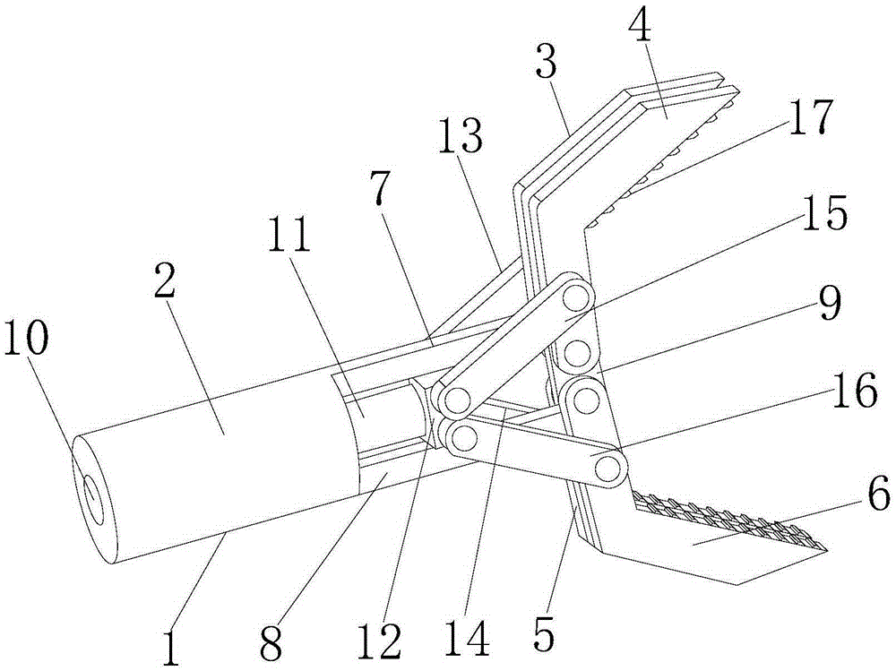
[0015] see figure 1 , the present invention provides a technical solution: a clamping device for maintenance and installation of electric equipment, including a clamping device body 1, the clamping device body 1 is Y-shaped, and the clamping device body 1 includes a mechanical arm 2, a first The clamping arm 3, the second clamping arm 4, the third clamping arm 5 and the fourth clamping arm 6, and one end of the mechanical arm 2 are respectively integrally formed with a ...


PUM


Abstract

The invention discloses a clamping device for electrical equipment overhauling and installing. The clamping device comprises a clamping device body, and the clamping device body comprises a mechanical arm, a first clamping arm, a second clamping arm, a third clamping arm and a fourth clamping arm; a first connecting column and a second connecting column are integrally molded at one end of the mechanical arm, and one end, far away from the mechanical arm, of the first connecting column is hinged to the first clamping arm on one side far away from the mechanical arm, the second clamping arm and one end of a center connecting plate through pins; and a hydraulic cylinder is arranged inside the mechanical arm, and a hydraulic stretching rod is arranged in the hydraulic cylinder. By means of the clamping device for electrical equipment overhauling and installing, any degree-of-freedom motion of a clamped object in a certain space can be achieved, the opening and closing angles of the clamping arms are large, the clamped object can be lifted to a working platform quite easily, potential safety hazards in electricity overhauling and installing are reduced, and the clamping device is simple in structure and convenient to operate.

Description

technical field [0001] The invention relates to the technical field of electric equipment, in particular to a clamping device for the maintenance and installation of electric equipment. Background technique [0002] Maintaining the safe operation of power equipment is an important guarantee for industrial and residential electricity consumption. Therefore, in order for the power equipment to operate normally, it is often necessary to overhaul the power equipment. In the process of overhauling and installing electrical equipment, workers often need to carry necessary tools or other devices to work at heights, which is very inconvenient to carry and also poses a great safety hazard. [0003] The clamping device for the maintenance and installation of electric equipment disclosed in the Chinese invention patent application publication CN204019400U, when the device is working in the hydraulic cylinder, drives the push rod to move back and forth, thereby driving the V-shaped conn...

Claims


Application Information

Patent Timeline
Patent Type & Authority Applications(China)
IPC IPC(8): B25J15/08H02G1/02
Inventor 陈小英
Owner 常州亚各来德机电设备制造有限公司
Why Eureka
Try Eureka