
A humanoid robot knee joint capable of active and semi-passive actuation

A humanoid robot and semi-passive technology, applied in the field of humanoid robots, can solve the problems of uncontrollable motion, low energy efficiency, and the inability of active and passive knee joints to achieve dynamic and efficient motion.

Active Publication Date: 2017-03-08
HARBIN INST OF TECH
View PDF9 Cites 0 Cited by
  • Summary
  • Abstract
  • Description
  • Claims
  • Application Information

AI Technical Summary

Problems solved by technology

[0003] The present invention aims to solve the problems that the active knee joints of existing robots cannot use their passive characteristics when walking, the energy efficiency is low, and the passive knee joints are not driven, so their motions are uncontrollable, and the active and passive knee joints cannot realize dynamic and efficient motion, and further provides A humanoid robot knee joint capable of active and semi-passive actuation

Method used


Image

  • A humanoid robot knee joint capable of active and semi-passive actuation
  • A humanoid robot knee joint capable of active and semi-passive actuation
  • A humanoid robot knee joint capable of active and semi-passive actuation

Examples


specific Embodiment approach 1

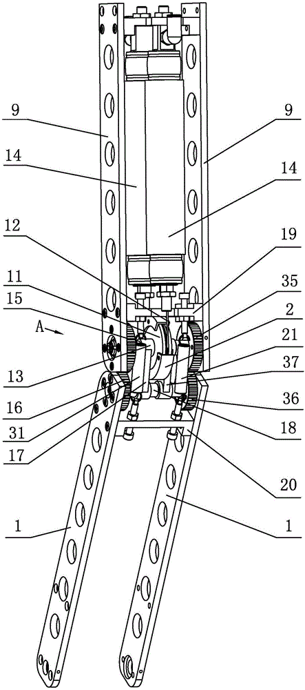
[0013] Specific implementation mode one: combine figure 1 Explain that a humanoid robot knee joint capable of active and semi-passive driving in this embodiment includes a driving mechanism and a transmission mechanism; the driving mechanism includes a transmission wheel 11, a steel wire rope 12, a first rotating shaft 13, and a first spring support 19. A second spring support 20, a tension spring 21 and two pneumatic artificial muscles 14;

[0014] The transmission mechanism includes a central gear 15, a planetary gear 16, a tie rod 17 and a second rotating shaft 18;

[0015] The two pneumatic artificial muscles 14 are arranged in an antagonistic manner, and the upper ends of the two pneumatic artificial muscles 14 are connected to the thigh 9; a central gear 15 is fixed on the thigh 9, and the first rotating shaft 13 is mounted on a central gear 15 through bearing rotation superior;

[0016] A planetary gear 16 is fixed on the calf 1, the second shaft 18 is rotatably mount...

specific Embodiment approach 2

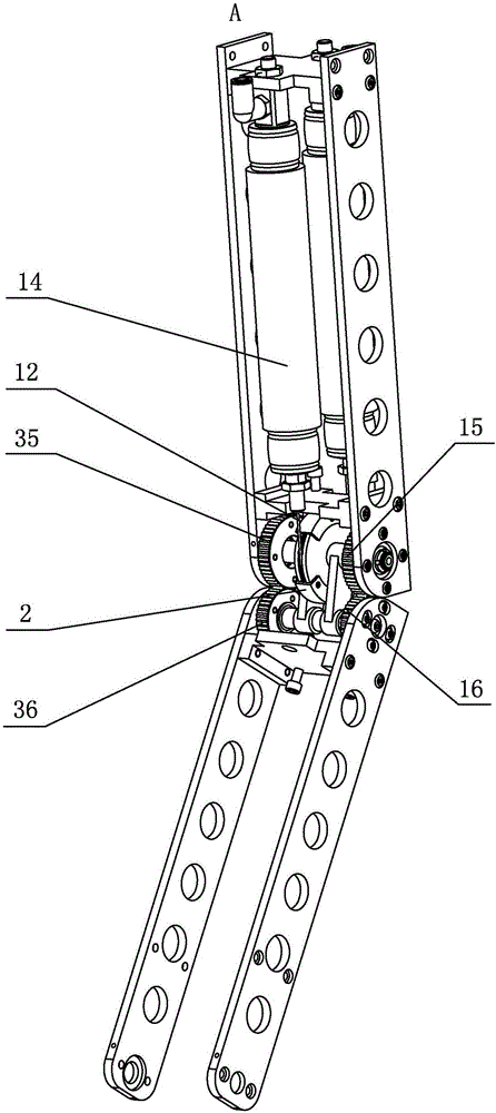
[0019] Specific implementation mode two: combination figure 1 and figure 2 Explain that a kind of humanoid robot knee joint that can realize active and semi-passive driving described in this embodiment also includes another sun gear 35 and another planetary gear 36; a sun gear 15 and another sun gear 35 are arranged on the transmission On both sides of the wheel 11, another central gear 35 is fixed on the thigh 9, a planetary gear 16 and another planetary gear 36 are arranged on both sides of the transmission wheel 11, and another planetary gear 36 is fixed on the shank 1. A rotating shaft 13 is rotatably mounted on another sun gear 35 through a bearing, the second rotating shaft 18 is rotatably mounted on another planetary gear 36 through a bearing, and the other sun gear 35 meshes with another planetary gear 36 . Such setting can reduce the clearance fit between the sun gear and the planetary gear, maintain balance, and ensure the stable and reliable operation of the knee ...

specific Embodiment approach 3

[0020] Specific implementation mode three: combination figure 1 Explain that a humanoid robot knee joint that can realize active and semi-passive driving described in this embodiment also includes another tension spring 31; another tension spring 31 is arranged on the other side of the transmission wheel 11, and the other The upper end of the tension spring 31 is connected with the first spring bracket 19 , and the lower end of the other tension spring 31 is connected with the second spring bracket 20 . Such a setting is conducive to providing sufficient driving force in the semi-passive sports mode. Others are the same as in the second embodiment.


PUM


Abstract

A humanoid robot knee joint capable of realizing active and semi-passive driving relates to a humanoid robot knee joint, and solves the problems that the active knee joint of the existing robot cannot make use of its passive property while walking, has low energy efficiency and the passive knee joint is not driven, the movement of the passive knee joint is uncontrollable, the active and passive knee joints cannot realize dynamic and efficient movement. The humanoid robot knee joint comprises a driving mechanism and a transmission mechanism. The driving mechanism comprises a transmission wheel, a steel wire rope, a first rotation shaft, a first spring bracket, a second spring bracket, an extension spring and two pneumatic artificial muscles. The transmission mechanism comprises a central gear, a planetary gear, a tie bar and a second rotation shaft. The first spring bracket is installed on a thigh above the central gar, and the second spring bracket is installed on a shank under the planetary gear. Two ends of the extension spring are connected with the first spring bracket and the second spring bracket respectively. The humanoid robot knee joint of the present invention is used for a humanoid robot.

Description

technical field [0001] The invention relates to a humanoid robot knee joint, which belongs to the field of humanoid robots. Background technique [0002] The study of human biomechanics shows that the human knee joint has both active and passive driving modes, which can assist the human body to complete various sports such as walking, running, and jumping. During walking, knee flexion, that is, the bending of the calf backwards, is usually driven by muscle tissue; knee extension, that is, the forward swing and straightening of the calf, is usually completed by passive power such as inertia, so the energy efficiency of human walking is very high . When running and jumping, the knee joint is driven by musculature to provide sufficient power and drive. At present, the knee joints of robots can generally be divided into two types—active knee joints and passive knee joints. Active knee joints use motors and other driving devices to provide the driving force required for movemen...

Claims


Application Information

Patent Timeline
Patent Type & Authority Patents(China)
IPC IPC(8): B25J17/02
Inventor 臧希喆刘义祥刘鑫宇赵杰
Owner HARBIN INST OF TECH
Learn More