Wind driven generator and wind generating set

A technology of wind power generators and wind power generators, which is applied in the direction of wind power motor combination, wind power engine, wind power generation, etc. It can solve the problems of uneven air gap and other problems, and achieve the prevention of air gap change, the reduction of axial distance, and the relative displacement Reduced effect

Active Publication Date: 2016-02-03
BEIJING GOLDWIND SCI & CREATION WINDPOWER EQUIP
View PDF4 Cites 6 Cited by
  • Summary
  • Abstract
  • Description
  • Claims
  • Application Information

AI Technical Summary

Problems solved by technology

[0006] The embodiment of the present invention provides a wind power generator and a wind power generating set to solve the problem that the air gap of the generator of the wind power generating set in the prior art is easy to be uneven during use

Method used


Image

  • Wind driven generator and wind generating set
  • Wind driven generator and wind generating set
  • Wind driven generator and wind generating set

Examples


Embodiment 1

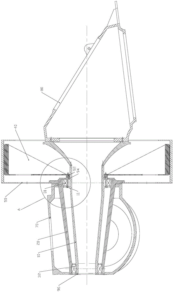
[0031] Such as Figure 2 to Figure 4 As shown, in this embodiment, the wind power generator includes a fixed shaft 10 , a moving shaft 20 , a bearing assembly, a stator 40 and a rotor 50 . The fixed shaft 10 is used to carry other components. The moving shaft 20 is sleeved on the fixed shaft 10 through a bearing assembly, and can rotate relative to the fixed shaft 10 . The bearing assembly includes a first bearing 31 , the inner ring of the first bearing 31 is fixedly arranged on the fixed shaft 10 , and the outer ring of the first bearing 31 is fixedly connected with the moving shaft 20 , so that the moving shaft 20 can rotate relative to the fixed shaft 10 . The stator 40 is fixedly connected to the inner ring of the first bearing 31 . The rotor 50 is fixedly connected to the moving shaft 20 , and the position of the rotor 50 on the moving shaft 20 corresponds to the first bearing 31 along the radial direction.

[0032] Since the stator 40 is fixed on the inner ring of th...

Embodiment 2

[0047] Such as Figure 5 and 6 As shown, in this embodiment, except for the arrangement positions of the fixed shaft flange 11 and the sealing ring 94, the structure and arrangement positions of other components are the same as those in the first embodiment.

[0048] In this embodiment, the fixed shaft flange 11 is located between the first bearing 31 and the stator 40 . The fastening bolts 92 pass through the threaded holes on the stator 40 , the fixed shaft flange 11 and the inner ring of the first bearing 31 in sequence. The fastening bolt 92 is clearance fit with the hole on the fixed shaft flange 11 and the hole on the stator 40 .

[0049] The sealing ring 94 is sleeved on the peripheral surface of the fixed shaft flange 11, and seals the gap 91 between the peripheral surface of the fixed shaft flange 11 and the bearing cover 93 (see Figure 4 ),Such as Figure 5 As shown, the bearing cover 93 is fixedly connected to the end of the moving shaft 20 close to the stator ...


PUM


Abstract

The invention provides a wind driven generator and a wind generating set. The wind driven generator comprises a fixed shaft, a movable shaft, a stator and a rotor. The movable shaft is arranged on the fixed shaft in a sleeving manner through a bearing assembly and can rotate relative to the fixed shaft; the bearing assembly comprises a first bearing, the inner ring of the first bearing is fixedly arranged on the fixed shaft, and the movable shaft is fixedly connected to the outer ring of the first bearing; the stator is fixedly connected to the inner ring of the first bearing; and the rotor is fixedly connected to the movable shaft, and the position of the rotor on the movable shaft corresponds to the first bearing in the radial direction. The wind driven generator can well ensure the air gap uniformity in the running process, and the weight of the fixed shaft does not need to be increased.

Description

technical field [0001] The invention relates to the field of wind power generating equipment, in particular to a wind power generator and a wind power generating set. Background technique [0002] Such as figure 1 As shown, a wind power generator generally includes a tower, a base 3, a wind generator and an impeller. Among them, the tower is used to support other components. The base is used to connect the wind turbine and the tower, and can also carry other components. The wind generator is mainly used to convert mechanical energy into electrical energy, which includes a fixed shaft 4 fixed on the base 3, a stator 1 fixed on the fixed shaft 4, a rear bearing 5 and a front bearing sleeved on the fixed shaft 4, The moving shaft 8 set on the fixed shaft 4 through the rear bearing 5 and the front bearing sleeve, the rotor 2 fixed on the moving shaft 8, the rear end cover 6 fixed on the moving shaft 8, etc., between the stator 1 and the rotor 2 air gap. The impeller is used...

Claims


Application Information

Patent Timeline
IPC IPC(8): F03D9/25F03D15/20
CPCY02E10/72F03D80/70F16C35/06F16C2361/31Y02E10/70
Inventor 孙涛朱兵
Owner BEIJING GOLDWIND SCI & CREATION WINDPOWER EQUIP
Why Eureka
Try Eureka