Upper die for fastening button

a technology for fastening buttons and dies, which is applied in the field of upper dies for fastening buttons, can solve the problems of preventing the post from passing through the cloth smoothly, and achieve the effect of reducing the amount of deformation of the elastic member associated with increasing load

Active Publication Date: 2017-03-21
YKK CORP
View PDF18 Cites 0 Cited by
  • Summary
  • Abstract
  • Description
  • Claims
  • Application Information

AI Technical Summary

Benefits of technology

[0008]In the invention, by providing the annular recess in the elastic member, which is recessed radially outward from the inner surface of the elastic member at e.g. the middle of the inner surface in the axial direction, the elastic member is sectioned into a thin-walled section which is located radially outward from the recess, and two or more thick-walled sections which remain above and below, in the axial direction, the recess and the thin-walled section. Thereby, at the time of piercing the cloth when a load lower than that at the time of swaging the post is being imposed on the elastic member, the thin-walled section of the elastic member will be mainly deformed so as to absorb the load (the thick-walled sections would be partially deformed following the thin-walled section). Just after piercing the cloth, the elastic member is temporarily restored to release part of the load. After that, at the time of swaging the post, a load higher than that at piercing is being imposed on the elastic member. At this time, the thin-walled section of the elastic member will be first deformed more than the amount of deformation at the time of piercing the cloth, and then the thick-walled sections will begin to be deformed to absorb the load substantially after they have come in contact with or close to each other. Therefore, it is possible to make the flexibility of the elastic member different between at piercing and at swaging.
[0012]In an embodiment of the invention, at the time of the post piercing the cloth, at the time of swaging the post, the axial space of the recess in the elastic member reduces so as for the thick-walled sections axially adjacent to come close to each other. That is, with the load in the axial direction at swaging, the elastic member is deformed, and thereby the recess collapses such that the thick-walled sections above and below the recess approach or contact each other. After this approach of the thick-walled sections, the amount of deformation of the elastic member associated with increasing load will reduce.

Problems solved by technology

If the flexibility of the elastic member is changed in order to reduce the load imposed on the upper die etc. at the swaging, a defect such as buckling of the post would occur at the cloth-piercing time, preventing the post from passing through the cloth smoothly.

Method used


Image

  • Upper die for fastening button
  • Upper die for fastening button
  • Upper die for fastening button

Examples


Embodiment Construction

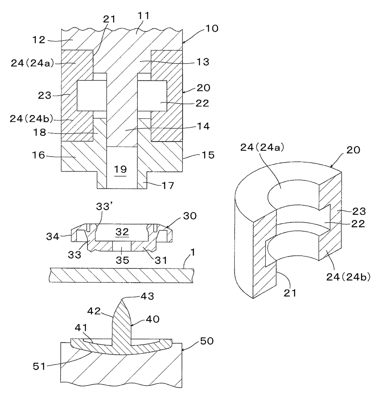
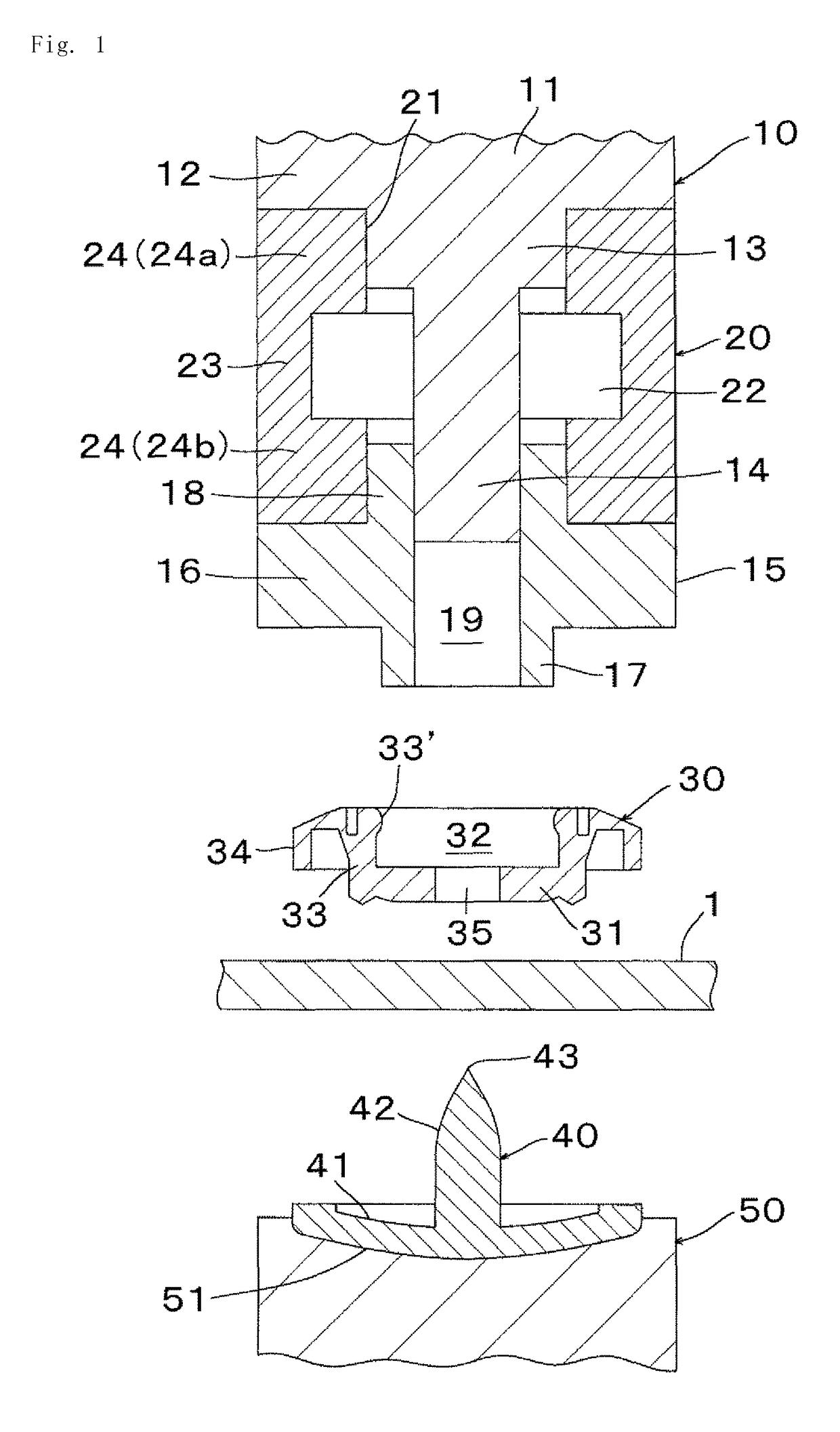
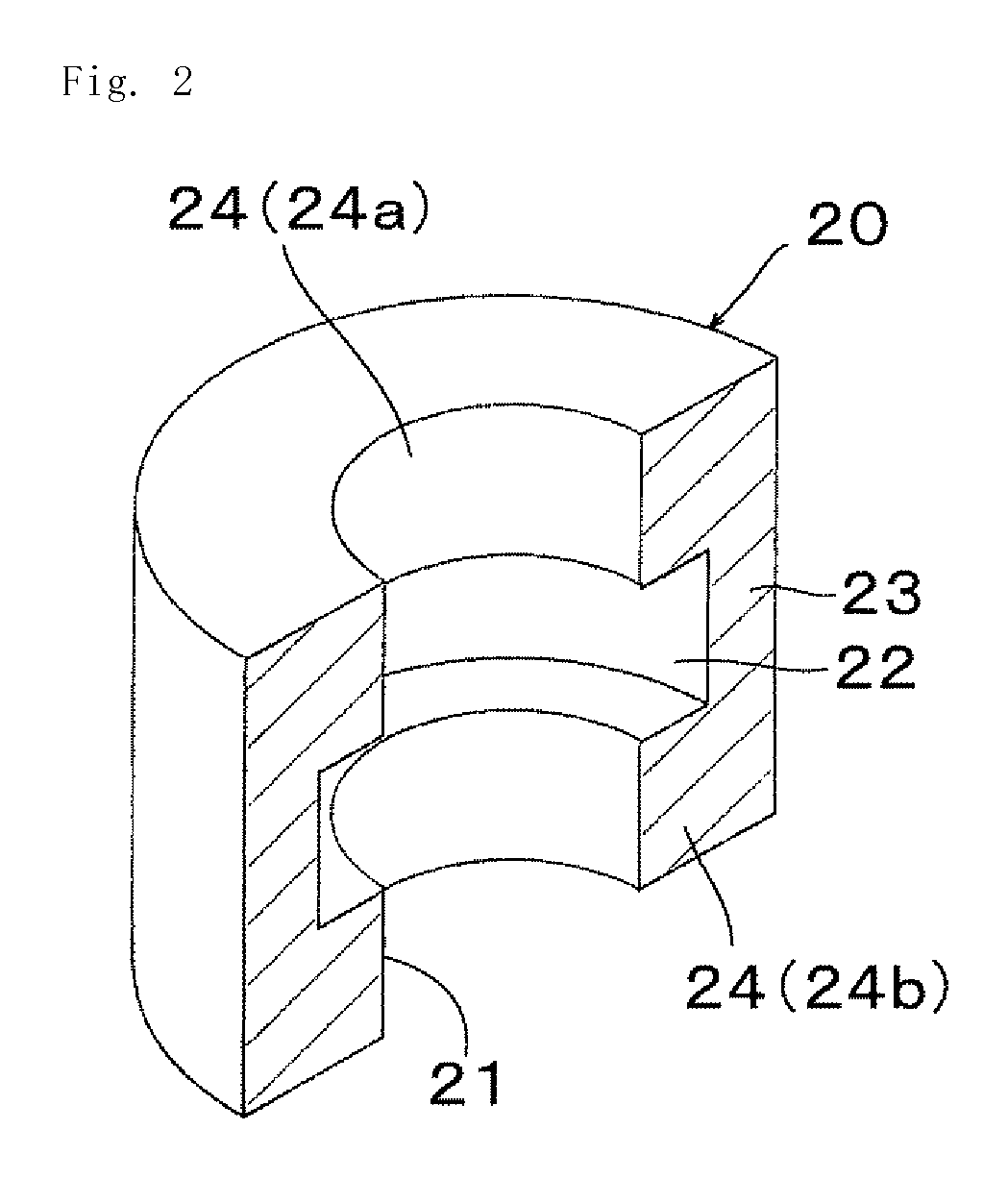
[0031]Hereinafter, preferred embodiments of the invention will be described with reference to the drawings. FIG. 1 shows an arrangement in the axial direction (up-and-down direction) of, from above, a button-fastening upper die (hereinafter referred to simply as “upper die”) 10 in accordance with an embodiment of the present invention; a female snap button (hereinafter referred to simply as “button”) 30 as one example of buttons; a fabric 1; a button fastener 40; and a lower die 50 when the button 30 is about to be fastened to the cloth 1. The upper die 10 comprises a die body 11 made of steel, an upper part unshown of which is connected to an up-and-down part of a button-fastening press machine (now shown); a button-holding member 15 made of metal to hold the button 30 at the time of fastening the button; and a cylindrical elastic member (spring) 20 made of urethane rubber disposed between the die body 11 and the button-holding member 15. The die body 11 includes a disk-shaped uppe...


PUM

PropertyMeasurementUnit
timeaaaaaaaaaa
elasticityaaaaaaaaaa
flexibilityaaaaaaaaaa

Abstract

A button-fastening upper die includes a die body, a button-holding member and a cylindrical elastic member arranged between the die body and the button-holding member. By providing the elastic member with an annular recess recessed radially outward from the inner surface e.g. at the middle of the surface, the elastic member is sectioned into a thin-walled section located radially outward from the recess and two or more thick-walled sections remaining above and below the recess and the thin-walled section.

Description

[0001]This application is a national stage application of PCT / JP2009 / 071680 which is incorporated herein by reference.BACKGROUND OF THE INVENTION[0002]The present invention relates to an upper die for fastening a button, and more specifically, to an upper die for use in fastening a button such as a snap button and a decorative button, to a cloth using a button fastener.[0003]When a button such as a male snap button, a female snap button, a decorative button is fastened to a cloth by swaging a post of a button fastener, an upper die is generally used. Such an upper die, as disclosed in e.g. JP,H11-1812,A, is connected to an up-and-down part of a button-fastening press machine. The upper die comprises a die body (swaging punch) having a columnar punch to swage the post of a button fastener, a button-holding member (guide punch) to hold a button at the time of fastening the button, the button-holding member having a center bore to pass the punch therethrough, a cylindrical elastic memb...

Claims


Application Information

Patent Timeline
Patent Type & Authority Patents(United States)
IPC IPC(8): A41H37/00B29C65/64B29C65/60B21J15/02B29C65/00B29L19/00
CPCA41H37/00B21J15/02B21J15/025B29C65/606B29C65/64B29C66/304B29C66/474B29C66/742B29C66/81431B29C66/81611B29C66/83221B29C66/9231B29C66/9292B29C66/729B29C66/7294B29C66/81423B29C2793/0045B29L2019/00Y10T156/1309B29C66/1122
Inventor HASEGAWA, KENJISUGIYAMA, HIROYUKI
Owner YKK CORP
Why Eureka
Try Eureka