Rotating electric machine with one-sided cooling and method for one-sided cooling

A technology for rotating electric machines and cooling air, applied in cooling/ventilation devices, electromechanical devices, electrical components, etc., which can solve problems such as long structural lengths, and achieve the effects of saving costs and reducing complexity

Inactive Publication Date: 2019-03-22
SIEMENS AG
View PDF13 Cites 0 Cited by
  • Summary
  • Abstract
  • Description
  • Claims
  • Application Information

AI Technical Summary

Problems solved by technology

This requires a longer structure length

Method used


Image

  • Rotating electric machine with one-sided cooling and method for one-sided cooling
  • Rotating electric machine with one-sided cooling and method for one-sided cooling
  • Rotating electric machine with one-sided cooling and method for one-sided cooling

Examples


Embodiment Construction

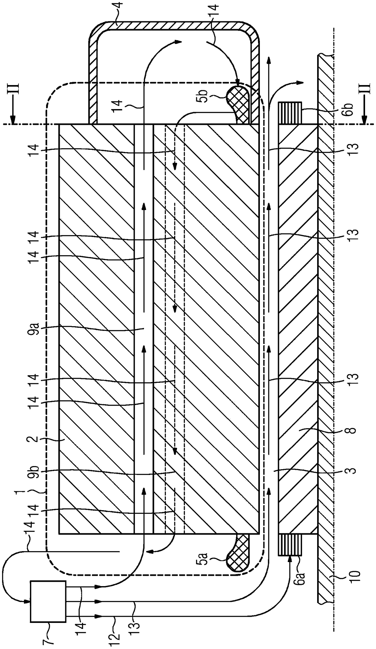
[0025] figure 1 A longitudinal sectional view of a first embodiment of a rotating electrical machine is shown, which is rotationally symmetrical in the axial direction, wherein only the upper part of the machine is shown. Such machines, especially motors, have a power of more than 10 megawatts and a diameter of more than 5 meters. The rotating electrical machine has a stator 1 with a stator lamination stack 2 , a front stator winding head 5 a and a rear stator winding head 5 b. Furthermore, the rotating electrical machine has a rotor 8 with a front rotor winding head 6 a and a rear rotor winding head 6 b and a shaft 10 . The hydrodynamic machine 7 produces a cooling air flow 12 , 13 , 14 , in particular under pressure, by means of which the machine is cooled on one side. The front rotor winding head 6 a and the front stator winding head 5 a are directly cooled by means of a third cooling air flow 12 , while a first cooling air flow 13 passes from the pressure side of the hyd...


PUM


Abstract

The invention relates to a rotating electrical machine having a stator (1), a rotor (8) and a hydrodynamic machine (7) provided for cooling the rotating electrical machine on one side, wherein the stator (1) has a stator lamination stack (2), front stator winding head (5a) and rear stator winding head (5b), wherein the rotor (8) has a rear rotor winding head (6b). In order to improve cooling in the case of one-sided ventilation compared to the prior art, in particular with regard to a uniform temperature distribution, it is proposed that the stator lamination pack (2) has channels (9a, 9b) extending in the axial direction, which are provided for cooling of the rear stator winding head (5b) by means of a second cooling air flow (14) generated by the hydrodynamic machine (7), wherein at least one first channel (9a) is provided for the second cooling air flow (14) generated by the hydrodynamic machine (7) The cooling air flow (14) is directed through the stator lamination stack (2) to the rear stator winding head (5b), where the air is fixed on the side of the stator lamination stack (2) on the side of the rear stator winding head (5b) A guide device (4) provided for routing a second cooling air flow (14) via the rear stator winding head (5b), wherein at least one second channel (9b) is provided for routing the second cooling air flow ( 14) Leading from the rear stator winding head (5b) back through the stator lamination stack (2), wherein at least two radial cutouts (11) arranged in the axial direction in each case are provided for cooling the stator lamination stack (2 ), in particular the stator winding and / or the rear rotor winding head (6b), wherein the radial cutouts are arranged radially in the passages (9a, 9b) extending in the axial direction and between the stator laminations (2) and the rotor (8 ) between the air gaps (3) and connect the two to each other, wherein the axial spacing between the radial cutouts (11) is towards the side of the stator lamination stack (2) facing away from the hydrodynamic machine (7) Smaller and set to compensate for temperature gradients created by one-sided cooling.

Description

technical field [0001] The invention relates to a rotating electrical machine with a stator, a rotor and a hydrodynamic machine, which is provided for cooling the rotating electrical machine on one side, wherein the stator has a stator lamination stack, a front stator winding head and a rear stator winding head, In this case the rotor has a rear rotor winding head. Background technique [0002] The invention relates to the field of large electrical machines. For cooling purposes, such large machines, such as in particular ring motors for gearless cement tube mills or for reducing copper ore, must be ventilated from the outside due to the low rotational speed of the motors. For this purpose, the cooling air is either drawn from the environment via a filter or recooled in the circuit via an air-to-water cooler. In this case, the cooling air flow must be forced against the motor via different channels by means of one or more hydrodynamic machines with fans, which are driven s...

Claims


Application Information

Patent Timeline
Patent Type & Authority Patents(China)
IPC IPC(8): H02K1/20H02K9/04H02K9/10
CPCH02K1/20H02K9/04H02K9/10H02K2209/00
Inventor 弗兰克·赛比克
Owner SIEMENS AG
Why Eureka
Try Eureka