Buckle assembly

A buckle and female buckle technology, applied in the direction of quick-action fasteners, etc., can solve the problems of loose connection between the female buckle and the female buckle, small thickness range of the buckle, poor installation and disassembly, etc., so that it is not easy to loosen and convenient for employees Operation, performance and reliable results

Inactive Publication Date: 2016-02-03
SAIC-GM-WULING AUTOMOBILE CO LTD
View PDF8 Cites 5 Cited by
  • Summary
  • Abstract
  • Description
  • Claims
  • Application Information

AI Technical Summary

Problems solved by technology

[0002] The existing structure and installation method: the buckle and sub-buckle are mostly thread structure: the mold structure is complex, the force required for the movement and reset of the sub-buckle is very large, and the installation and disassembly are poor; Produces permanent deformation and cannot be reused; the range of clamping thickness is small
[0003] The prior art has published a buckle with the patent number: 200820055290.X, which includes a sub-buckle and a female buckle. The female buckle is two detachable legs. When fixing the product, the fastening surface between the female buckle and the product is smooth. The surface of the female buckle is easy to fall off and the installation is not firm; moreover, the inner surface of the female buckle expands and opens the structure as a guide, and the two legs are in a state of long-term expansion during installation, which is prone to permanent deformation and is not conducive to repeated use.
[0004] At the same time, the undercut structure is installed on the sub-button, and the inner surface of the female buckle is also a smooth structure. When encountering external force collision or shaking, it is easy to squeeze the feet, causing the sub-button to shrink inwardly, so that the sub-button The connection with the female buckle is loose, resulting in the situation that it cannot be fastened

Method used


Image

  • Buckle assembly
  • Buckle assembly
  • Buckle assembly

Examples


Embodiment Construction

[0020] The present invention will be described in further detail below in conjunction with the accompanying drawings and embodiments.

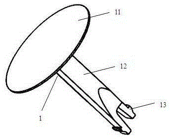
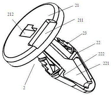
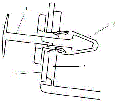
[0021] Such as Figure 1-2 As shown, the buckle fitting of the present invention includes a sub-button 1 and a female buckle 2 that can be snapped together. The sub-button 1 includes a pressing part 11, a guide post 12 and a limiting structure 13. The insertion end of the guide post 12, the pressing part 11 is located at the other end of the guide post 12, and the female button 2 includes a female button base 21, a guide part 22 and a step on the side of the guide part 22 The engaging part 23, the guide part 22 is provided on the female button base 21, the female button base 21 is provided with a through hole 212 for inserting the child button 1, and the guide part 22 is provided with a hollow part 221 , the through hole 212 corresponds to the hollow portion 221 , and the sub-buckle 1 is snapped into the hollow portion 221 .

[0022] With th...


PUM


Abstract

The invention provides a buckle assembly and belongs to the field of mounting and fastening structures. The buckle assembly comprises a secondary buckle and a primary buckle, wherein the secondary buckle and the primary buckle can be connected in a clamped mode. The secondary buckle comprises a pressing part, a guide post and a limiting structure. The limiting structure is arranged at the insertion end of the guide post. The pressing part is arranged at the other end of the guide post. The primary buckle comprises a primary buckle base, a guide part and a step clamping part arranged on the side edge of the guide part. The guide part is arranged on the primary buckle base. The primary buckle base is provided with a through hole for the secondary buckle to be inserted in. The guide part is provided with a hollow portion. The through hole corresponds to the hollow portion. The secondary buckle is connected in the hollow portion in a clamped mode. The buckle assembly has the beneficial effects of being capable of being used repeatedly, low in cost, not liable to generate permanent deformation, suitable for fastening base materials of different thicknesses, reliable in performance and easy to dismount.

Description

technical field [0001] The invention relates to an installation and fastening structure, in particular to a snap fitting. Background technique [0002] The existing structure and installation method: the buckle and sub-buckle are mostly thread structure: the mold structure is complex, the force required for the movement and reset of the sub-buckle is very large, and the installation and disassembly are poor; It produces permanent deformation and cannot be reused; the range of clamping thickness is small. [0003] The prior art has published a buckle with the patent number: 200820055290.X, which includes a sub-buckle and a female buckle. The female buckle is two detachable legs. When fixing the product, the fastening surface between the female buckle and the product is smooth. In addition, the inner surface of the expansion structure of the female buckle is used as a guide, and the two legs are in a long-term expansion state during installation, which is prone to permanent d...

Claims


Application Information

Patent Timeline
Patent Type & Authority Applications(China)
IPC IPC(8): F16B21/08
Inventor 刘廷福丘昌州刘军舰贺康淼冯海萍
Owner SAIC-GM-WULING AUTOMOBILE CO LTD
Why Eureka
Try Eureka