High-pressure pollution discharge pneumatic valve

A pneumatic valve, high pressure technology, applied in the direction of lift valve, valve details, valve device, etc., can solve the problem that the valve core cannot be opened according to the design, reduce the exhaust pressure and final volume flow, and the valve core cannot be completely sealed, etc. To achieve the effect of easy guiding and positioning, reducing the possibility of dislocation, and avoiding the pressing force of the valve core

Active Publication Date: 2016-02-03
HEFEI GENERAL MACHINERY RES INST
View PDF7 Cites 1 Cited by
  • Summary
  • Abstract
  • Description
  • Claims
  • Application Information

AI Technical Summary

Problems solved by technology

[0003] Although the pneumatic valve is used in the high-pressure compressor blowdown system, it is more reliable and less costly than the direct use of high-pressure solenoid valve blowdown, but in the actual application process, it often occurs when the blowdown is not needed, and the valve core cannot be completely Sealing, there is leakage, which directly reduces the exhaust pressure and final volume flow of all levels; and there is a

Method used


Image

  • High-pressure pollution discharge pneumatic valve
  • High-pressure pollution discharge pneumatic valve
  • High-pressure pollution discharge pneumatic valve

Examples


Embodiment 1

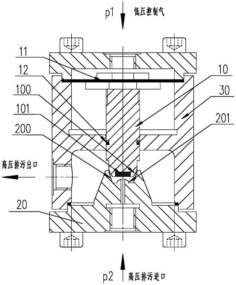
[0034] Such as figure 2 As shown, the outer edge of the sealing surface at the lower end of the valve core 10 is set as a valve core spherical surface 100, and the valve seat sealing position forms a tangential primary seal through the valve seat inclined guide surface 200 and the valve core spherical surface 100; The middle part of the sealing surface at the lower end of the valve core 10 is set as a polytetrafluoroethylene valve core filling block 101, and the valve seat sealing part is formed by the valve seat protrusion block 201 and the valve core filling block 101 to form a pneumatic valve along the valve core 10. Secondary sealing in the stroke direction, the valve core filling block 101 during the secondary sealing is blocked at the high-pressure sewage inlet of the pneumatic valve located on the valve seat raised block 201; that is, the sealing surface at the lower end of the valve core 10 is set It is a joint structure of the valve core spherical surface 100 and the...

Embodiment 2

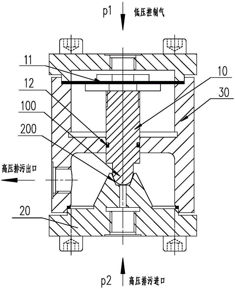
[0036] Such as image 3 As shown, the sealing surface at the lower end of the valve core 10 is set as a valve core spherical surface 100 as a whole, and the valve seat sealing part forms a tangential primary seal through the valve seat inclined guide surface 200 and the valve core spherical surface 100; The sealing part of the seat cooperates with the tangential contact of the spherical top surface of the valve core to form a secondary seal along the stroke direction of the valve core 10 .

[0037] In the above embodiment, the size of the inner cavity surrounded by the inclined guide surface 200 of the valve seat is larger than the spherical surface 100 of the valve core, so that the inclined guide surface 200 of the valve seat can completely accommodate the sealing surface of the lower end of the valve core 10 .

Embodiment 3

[0039] Such as Figure 4 , 5 As shown, the structure in embodiment 3 is relatively close to the structure in embodiment 2, the difference is that the head of the sealing surface at the lower end of the valve core 10 in embodiment 3 is set in a convex shape, and the convex head is set as It is just inserted in the high-pressure sewage inlet of the pneumatic valve, thereby improving the sealing effect compared with the structure in Embodiment 2.

[0040] The working principle of the pneumatic valve of the present invention will be described in further detail below in conjunction with the accompanying drawings.

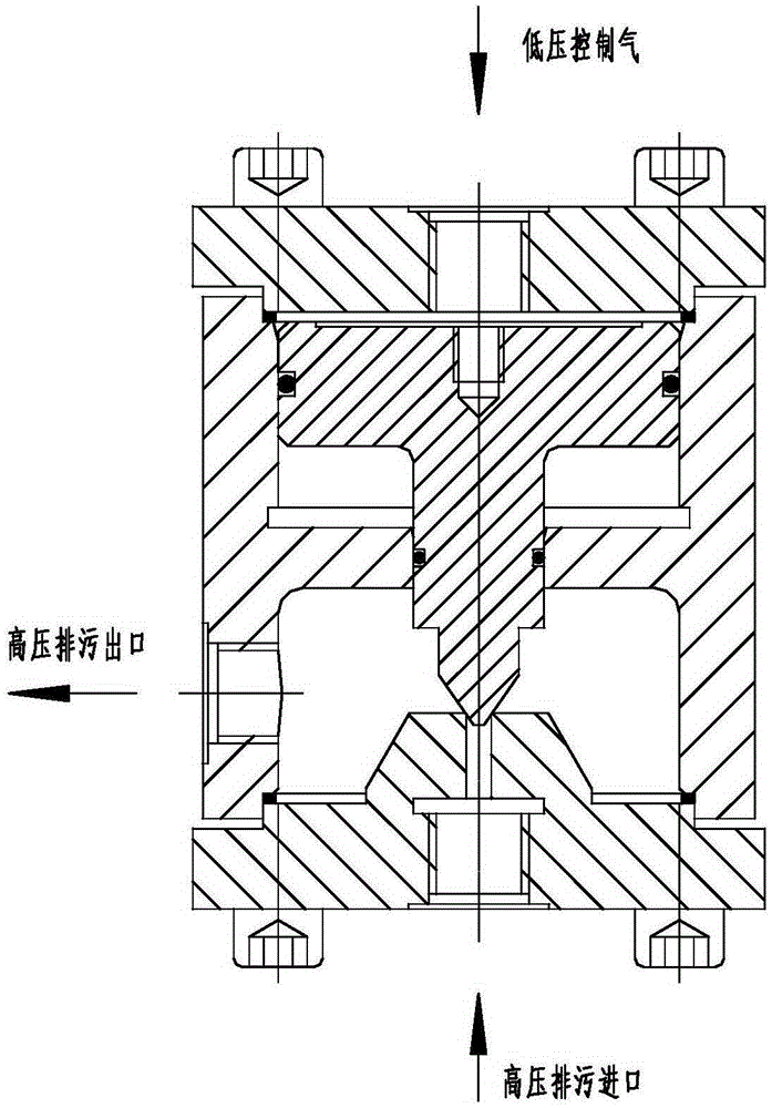
[0041]The high-pressure gas p2 enters from the bottom of the pneumatic valve and acts on the lower part of the valve core 10; the low-pressure control gas p1 enters from the top of the pneumatic valve and acts on the top of the valve core 10. During the air delivery process of the compressor, the action of p2 and p1 makes the valve core 10 and the valve seat 20 in a se...


PUM


Abstract

The invention discloses a high-pressure pollution discharge pneumatic valve. The high-pressure pollution discharge pneumatic valve comprises a valve element, a valve seat and a valve body. The valve element is of a diaphragm type structure penetrating a rubber diaphragm to be connected with the rubber diaphragm through a locknut. The valve element is provided with a Y-shaped sealing ring, and the frictional resistance of the sealing ring during motion of the valve element can be effectively controlled while sealing between the valve element and the valve body is achieved. A valve seat sealing part matched with the sealing face of the lower end of the valve element to form sealing fit is arranged on the valve seat. The outer edge of the sealing face of the lower end of the valve element is arranged as a valve element spherical surface. The valve seat sealing part is matched with the valve element spherical surface through a valve seat inclined guiding surface to form primary sealing in the tangential direction of the spherical surface. The middle of the sealing face of the lower end of the valve element is provided with a plastic valve element filling block, and the valve seat sealing part is matched with the valve element filling block through a valve seat protruding block to form secondary sealing in the stroke direction of the valve element. The sealing performance of the pneumatic valve can be remarkably improved, and the problem that the pneumatic valve is not smoothly opened is effectively solved.

Description

technical field [0001] The invention belongs to the technical field of blowdown valves, in particular to a high-pressure blowdown pneumatic valve. Background technique [0002] The high-pressure blowdown pneumatic valve is used in the blowdown system of the high-pressure compressor, and the discharge of the high-pressure gas-water-oil mixture is controlled by the discharge of the low-pressure control gas applied to the pneumatic valve. In the prior art, such as figure 1 As shown, the lower end of the pneumatic valve is connected to high-pressure exhaust gas, and the upper end is connected to low-pressure control air. Both air pressures can act on the valve core. The valve core and the middle partition of the valve body are also sealed by an O-ring; when no sewage is required, the upper end of the pneumatic valve is fed with low-pressure control air, which makes the upper end of the valve core receive greater pressure, and the valve core moves downward. When moving, the con...

Claims


Application Information

Patent Timeline
IPC IPC(8): F16K31/126F16K1/36F16K1/32
CPCF16K1/32F16K1/36F16K31/126
Inventor 鲍军张成彦李奇谭跃进秦滨李金禄毛京兵邢志胜
Owner HEFEI GENERAL MACHINERY RES INST
Why Eureka
Try Eureka