Switch circuit of power switching

A technology for switching switches and circuits, applied in the direction of output power conversion devices, electrical components, etc., to achieve isolation, solve system failures, and eliminate backflow phenomena

Active Publication Date: 2016-02-03
INST OF ACOUSTICS CHINESE ACAD OF SCI
View PDF5 Cites 7 Cited by
  • Summary
  • Abstract
  • Description
  • Claims
  • Application Information

AI Technical Summary

Problems solved by technology

Using the design method of isolated half-bridge gate driver—ADuM5230 plus NMOS switch tube, solves all the shortcomings of existing power switching switches, and improves the reliability and stability of power switching

Method used


Image

  • Switch circuit of power switching
  • Switch circuit of power switching
  • Switch circuit of power switching

Examples


Embodiment Construction

[0040]In order to make the purpose, technical solutions and advantages of the embodiments of the present invention clearer, the technical solutions in the embodiments of the present invention will be clearly and completely described below in conjunction with the drawings in the embodiments of the present invention. Obviously, the described embodiments It is a part of embodiments of the present invention, but not all embodiments. Based on the embodiments of the present invention, all other embodiments obtained by persons of ordinary skill in the art without making creative efforts belong to the protection scope of the present invention.

[0041] In order to facilitate the understanding of the embodiments of the present invention, further explanations will be given below with specific embodiments in conjunction with the accompanying drawings.

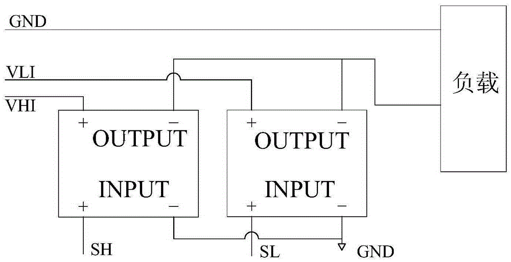
[0042] Figure 4 A power switch circuit provided for an embodiment of the present invention, such as Figure 4 As shown, the power swi...


PUM


Abstract

The present invention relates to a switch circuit of power switching. The switch circuit provided by the invention comprises: a logic gate conversion module, a first driving module, a second driving module, a first switch module and a second switch module. The logic gate conversion module is configured to convert input logic control signals into first logic driving signals and second logic driving signals; the first driving module is configured to output first switch signals and second switch signals according the first logic driving signals; the second driving module is configured to output third switch signals and fourth switch signals according to the second logic driving signals; and the first switch module is configured to output voltage to a load under the control of the first switch signals and the second switch signals, or the second module is configured to output voltage to the load under the control of the third switch signals and the fourth switch signals. According to the invention, the problem of the system fault caused by simultaneously conducting diverter switches because of the disordering of control signals is solved, the complete separation of the control signals and a heavy current is realized, and the weight of the system device is reduced; and moreover, the switch circuit of power switching has an important practical value.

Description

technical field [0001] The invention relates to the technical field of switching power supplies, in particular to a power switch circuit. Background technique [0002] The main function of the sonar transmitter is to generate a power signal with a specific form, which is actually a power conversion system, which is responsible for converting the DC power into a certain frequency of AC power for the load (transducer). For a specific load (transmitter), the size of the power signal is determined by the input voltage. For a transmitter with two power signals for high-power transmission and low-power transmission, it is required that the large and small power switch has a small power on the basis of high stability and reliability. switching power loss and high switching speed. [0003] For high-power transmission (several kilowatts) signals, the dry circuit current is nearly 100 amperes, which determines that conventional switches are no longer applicable. At present, the soli...

Claims


Application Information

Patent Timeline
Patent Type & Authority Applications(China)
IPC IPC(8): H02M1/092H02M1/38
Inventor 袁东玉朱昀马晓川鄢社锋刘大鹏
Owner INST OF ACOUSTICS CHINESE ACAD OF SCI
Why Eureka
Try Eureka