Logic conversion circuit device with cooling effect

A logic conversion and circuit device technology, which is applied in the direction of cabinet/cabinet/drawer parts, cooling/ventilation/heating transformation, etc., can solve the problem of poor operability, inability to realize the performance and force of closing the front cover no problem

Active Publication Date: 2016-02-03
江苏万邦微电子有限公司
View PDF4 Cites 0 Cited by
  • Summary
  • Abstract
  • Description
  • Claims
  • Application Information

AI Technical Summary

Problems solved by technology

With the introduction of logic conversion measures, the number of components will inevitably be increased. In addition, with the improvement of integration, the miniaturization trend of logic conversion circuit devices is also getting higher and higher, which will inevitably make the logic conversion circuit devices. The temperature rises, which affects the normal operation of the equipment, so it is necessary to introduce a radiator to dissipate heat. Usually such a radiator is a cabinet structure. By placing the logic conversion circuit device in the cabinet, and via the disk on the cabinet The internal heat dissipation pipe is used to realize the heat dissipation of the logic conversion circuit device. Specifically, the refrigerant is circulated through the refrigerant inlet and the refrigerant outlet connected to the heat dissipation pipe on the cabinet body, thereby cooling the logic conversion circuit. The heat generated by the device is absorbed and discharged, but now such radiators often have a front cover, which is used to open the cabinet of the radiator, and the front cover is arranged on the cabinet in sequence from high to low. Three rotating pai...

Method used


Image

  • Logic conversion circuit device with cooling effect
  • Logic conversion circuit device with cooling effect
  • Logic conversion circuit device with cooling effect

Examples


Embodiment Construction

[0027] Below in conjunction with accompanying drawing, content of the invention will be further described:

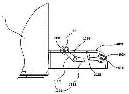
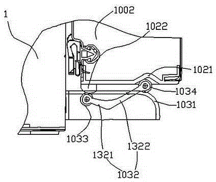
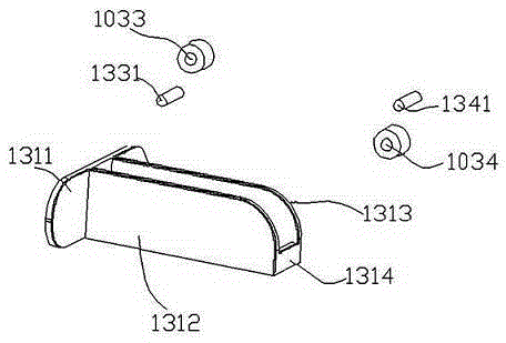
[0028] refer tofigure 1 , figure 2 , image 3 , Figure 4 and Figure 5 As shown, the logic conversion circuit device with a cooling effect includes a logic conversion circuit, and the logic conversion circuit is placed in a radiator, and the radiator is a hollow cabinet 1, and the cabinet 1 has a heat dissipation plate inside pipeline, the logic conversion circuit is arranged in the cabinet, and the cabinet 1 is provided with a refrigerant inlet and a refrigerant outlet connected to the heat dissipation pipe, and the refrigerant enters the refrigerant outlet through the refrigerant inlet Let the refrigerant flow out, and use this cycle to take away the heat generated by the logic conversion circuit. In addition, the cabinet 1 includes a front cover 1002 and a front cover attachment 1003. The front cover 1002 is opened Between the position where the cabinet body 1 ...


PUM


Abstract

The invention discloses a logic conversion circuit device with a cooling effect. A circuit port structure of a logic conversion circuit employs double-ring protection, and an NMOS tube part of the circuit is additionally provided with an ESM input layer. A bulged tail end forms a profile from the head to the tail from the low to the high, wherein the profile has slope. A left vertical-type sheet body is provided with a left hole which is disposed in the lateral direction of the left vertical-type sheet body and passes through the left vertical-type sheet body. A right vertical-type sheet body is provided with a right hole which is disposed in the lateral direction of the right vertical-type sheet body and passes through the right vertical-type sheet body. The above structure improves the ESD capability of a circuit port. Moreover, a protection diode is additionally disposed between the circuit and a power supply, thereby also improving the ESD capability of the circuit, and ironing out the defects in the prior art that a front cover plate is inclined when the front cover plate of the device is closed and the flexibility is poor.

Description

technical field [0001] The invention belongs to the technical field of conversion circuits, and in particular relates to a logic conversion circuit device with cooling effect. Background technique [0002] With the introduction of low-voltage logic, the problem of input / output logic inconsistency often occurs inside the system, which increases the complexity of system design. For example, when a 1.8V digital circuit communicates with an analog circuit operating at 3.3V, it is necessary to first solve the conversion problem of the two levels, and then a logic conversion circuit device is required. With the continuous emergence of digital ICs with different operating voltages, the necessity of logic conversion circuit devices is more prominent, and the logic conversion method will also change with the logic voltage, the form of the data bus, and the data transmission rate. With the introduction of logic conversion measures, the number of components will inevitably be increase...

Claims


Application Information

Patent Timeline
IPC IPC(8): H05K7/20H05K5/03
Inventor 朱勤辉张林窦延军张春秋
Owner 江苏万邦微电子有限公司
Why Eureka
Try Eureka