Commutation cell and compensation circuit therefor

A technology of rectification unit and compensation circuit, applied in the field of power electronics

Active Publication Date: 2016-02-03
TM4 INC
View PDF3 Cites 5 Cited by
  • Summary
  • Abstract
  • Description
  • Claims
  • Application Information

AI Technical Summary

Problems solved by technology

di / dt also produces significant and unwanted electromagnetic interference (EMI)

Method used


Image

  • Commutation cell and compensation circuit therefor
  • Commutation cell and compensation circuit therefor
  • Commutation cell and compensation circuit therefor

Examples


Embodiment Construction

[0054] Like reference numbers represent like features on the various figures.

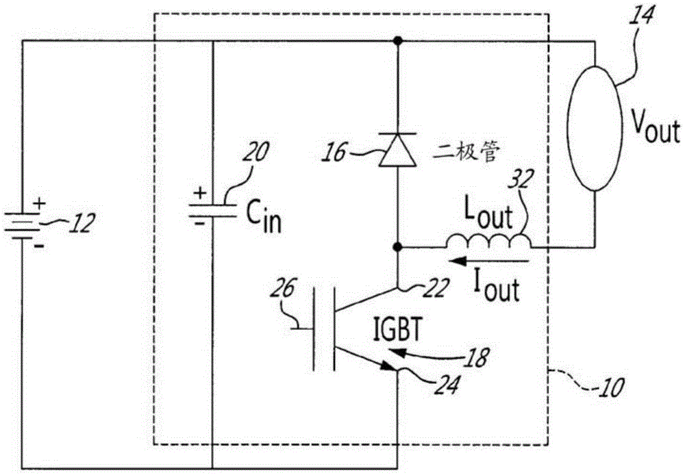
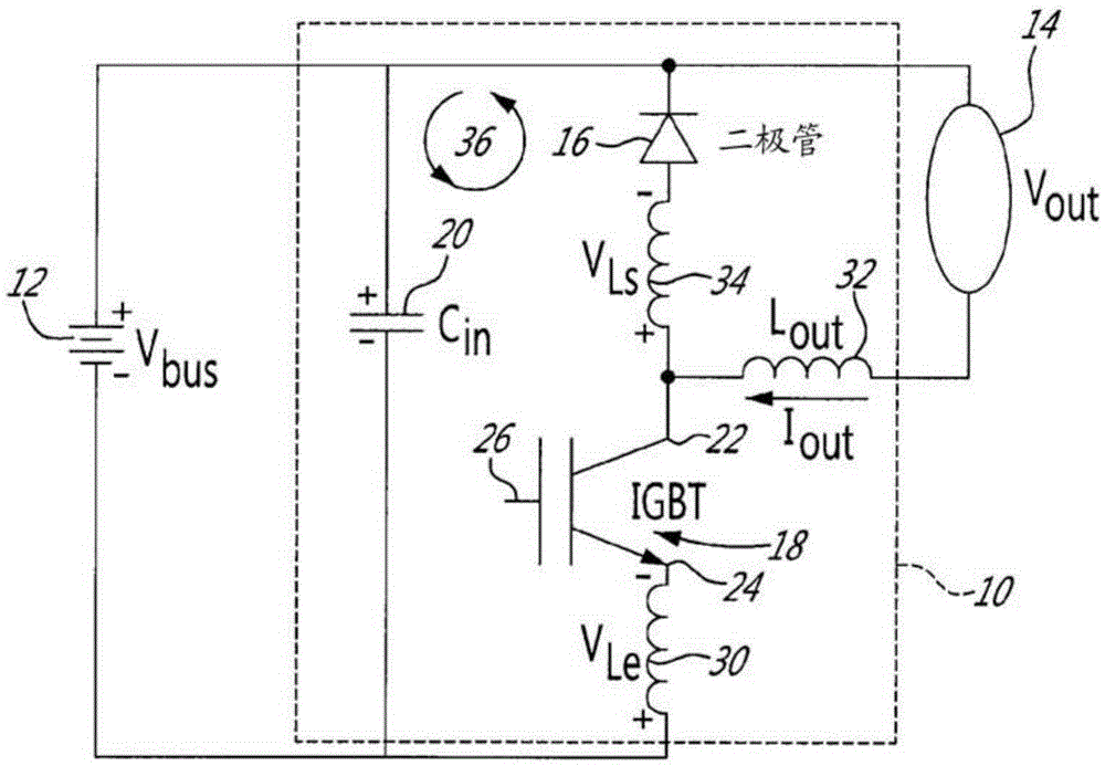
[0055] Various aspects of the present disclosure generally address one or more of the issues of overvoltage and recovery current currently present within the rectifier unit when switching.

[0056] In International Patent Publication No. WO2013 / 082705A1, International Patent Application No. PCT / CA2013 / 000805, U.S. Provisional Application Nos. 61 / 808,254 and 61 / 904,038, all by Jean-MarcCyr et al., and in http: / / www.advbe.com / docs / DeciElec2013-JeanMarc Cyr-TM4.pdf Available "ReducingswitchinglossesandincreasingIGBTdriveefficiencywithReflex TM gated driver technology" all describe circuits that can be used to limit the overvoltage in the rectifier unit, especially when the IGBT is turned off, and these disclosures are hereby incorporated by reference.

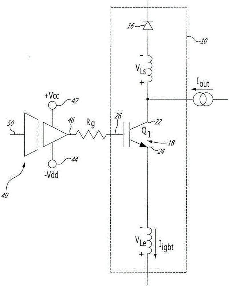
[0057] This technology controls the overvoltage and switching loss at turn-on and turn-on, and the reduction of the recovery current at turn-on of t...


PUM


Abstract

The present disclosure relates to a commutation cell and to a compensation circuit for limiting overvoltage across the power electronic switch of the commutation cell and for limiting a recovery current in a freewheel diode of the commutation cell. The power electronic switch has a parasitic emitter inductance. A variable gain compensation circuit generates a feedback from a voltage generated across the parasitic inductance of the emitter of the power switch at turn-on or turn-off of the power electronic switch. The compensation circuit provides the feedback to a control of the power electronic switch to reduce the voltage generated on the parasitic emitter inductance. A power converter including the commutation cell with the compensation circuit is also disclosed.

Description

technical field [0001] The present disclosure relates to the field of power electronics. More specifically, the present disclosure relates to a commutation cell configured to limit switch overvoltage when turning a power electronic switch on and off and to control the commutation cell's continuity when the power electronic switch is turned on. recovery current in the flow diode. The present disclosure also relates to a compensation circuit used in a rectification unit and a power converter including the rectification unit with the compensation circuit. Background technique [0002] Rectifier units are commonly used in electronic systems that require the conversion of voltage sources, including DC-DC converters and DC-AC converters, commonly referred to as converters. Due to the limited space left for power conversion circuits, such as those used in e.g. electric vehicle or hybrid vehicle applications, and in view of the high cost of semiconductors, there is an increasing n...

Claims


Application Information

Patent Timeline
Patent Type & Authority Applications(China)
IPC IPC(8): H03K17/08H02M1/32
CPCH03K17/166H03K17/168H03K17/082H03K17/567H01L2224/48091H01L2224/49111H01L2224/49175H01L2924/13055H01L2924/13091H01L2924/00014H01L2924/00H02M1/32H02P6/14H03K17/08
Inventor J-M.西尔M.埃尔雅各比P.弗勒里M.阿马尔
Owner TM4 INC
Why Eureka
Try Eureka