A processing mechanism for single-row bowling pins
A technology for a pin handling mechanism and bowling ball, which is applied to bowling balls, sports accessories, etc., can solve the problems of complex structure of bowling ball fitness equipment, large equipment area, and no equipment improvement research.
- Summary
- Abstract
- Description
- Claims
- Application Information
AI Technical Summary
Problems solved by technology
Method used
Image
Examples
specific Embodiment approach 1
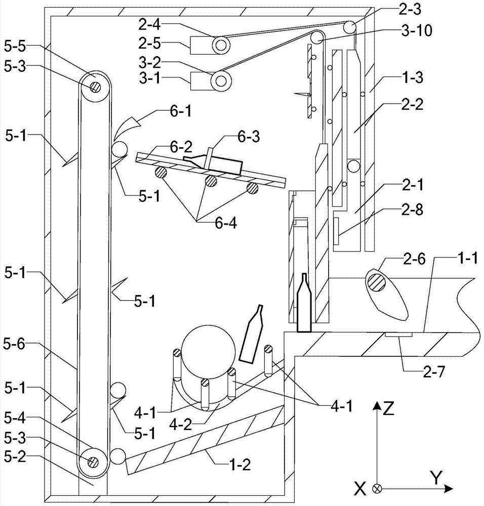
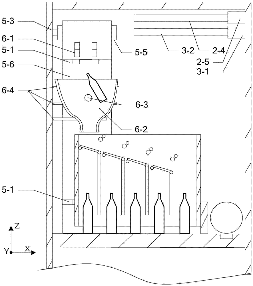
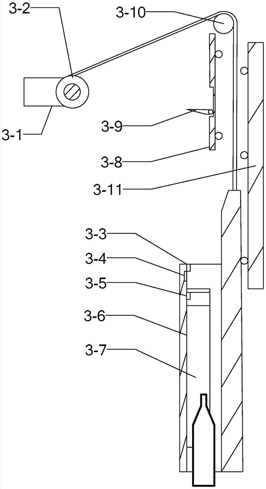
[0044] Specific implementation mode one: refer to Figure 1 to Figure 9 Specifically illustrate the present embodiment, a kind of single-row bowling pin processing mechanism described in the present embodiment, it comprises: frame, sweep bottle part, put bottle part, ball out part, ascend bottle part, send bottle part and controller;
[0045] The frame includes: goal lane 1-1, bottle groove 1-2 and shell;
[0046] The bottle sweeping part includes: bottle sweeper, bottle sweeper pulley 2-3, bottle sweeper pulley 2-4, bottle sweeper motor 2-5, bottle sweeper cam 2-6 and ball path positioning sensor 2-7, The bottle sweeper includes: bottle sweeper moving rod 2-1 and bottle sweeper fixed rod 2-2;
[0047] The bottle setting part includes: the pin setting basket motor 3-1, the pin setting basket belt pulley 3-2, the pin setting basket 3-6 and the pin setting basket pulley 3-10;
[0048] The ball out part includes: pin separation gate, ball out lane 4-2, flat belt 4-3, belt cam 4...
specific Embodiment approach 2
[0071] Specific embodiment two: this embodiment is a kind of single-row bowling pin processing mechanism described in specific embodiment one to be further explained, and in this embodiment, the controller includes the following units:
[0072] Falling ball positioning signal acquisition unit: collect the falling ball positioning signal output by the falling ball positioning sensor 4-6,
[0073] Falling ball judging unit: according to the falling ball positioning signal obtained by the falling ball positioning signal acquisition unit, it is judged whether there is a ball falling into the fairway 4-2,
[0074] Belt cam motor drive unit: When the ball falling judgment unit judges that a ball falls into the lane 4-2, it drives the belt cam motor to rotate,
[0075] Belt runner motor drive unit: When the falling ball judging unit judges that a ball falls into the fairway 4-2, it drives the belt runner motor to rotate,
[0076] Passing ball signal acquisition unit: collect the bow...
specific Embodiment approach 3
[0083] Specific embodiment three: this embodiment is a kind of single-row bowling pin processing mechanism described in specific embodiment one for further explanation, in this embodiment, the ball pin separation grid comprises: a plurality of ball pin separation columns 4-1 ;
[0084] The heads and ends of a plurality of pin separation columns 4-1 are respectively fixed on the inner walls of both sides of the shell, and the head ends are higher than the ends. The plurality of pin separation columns 4-1 are parallel to each other, and the two adjacent pins The distance between the separation columns 4-1 is larger than the diameter of the bowling pins and smaller than the diameter of the bowling balls.
PUM
 Abstract
Description
Claims
Application Information
 - R&D
- Intellectual Property
- Life Sciences
- Materials
- Tech Scout
- Unparalleled Data Quality
- Higher Quality Content
- 60% Fewer Hallucinations
Browse by: Latest US Patents, China's latest patents, Technical Efficacy Thesaurus, Application Domain, Technology Topic, Popular Technical Reports.
© 2025 PatSnap. All rights reserved.Legal|Privacy policy|Modern Slavery Act Transparency Statement|Sitemap|About US| Contact US: help@patsnap.com


