
Movable plate for injection molding apparatus

An injection molding device and moving plate technology, which is applied in the direction of manufacturing tools and presses, can solve the problems of mold damage, inability to adjust the level of the movable platen, and affect the accuracy of the mold, and achieve simple structure, low cost, and height adjustment The effect of compact structure

Active Publication Date: 2016-02-10
NISSEI PLASTIC IND CO LTD
View PDF10 Cites 6 Cited by
  • Summary
  • Abstract
  • Description
  • Claims
  • Application Information

AI Technical Summary

Problems solved by technology

If it is not level, it will affect the precision of the mold, and in severe cases, it will cause damage to the mold
[0005] However, in the structure of Patent Document 1, the levelness of the movable platen (1) cannot be adjusted

Method used


Image

  • Movable plate for injection molding apparatus
  • Movable plate for injection molding apparatus
  • Movable plate for injection molding apparatus

Examples


Embodiment

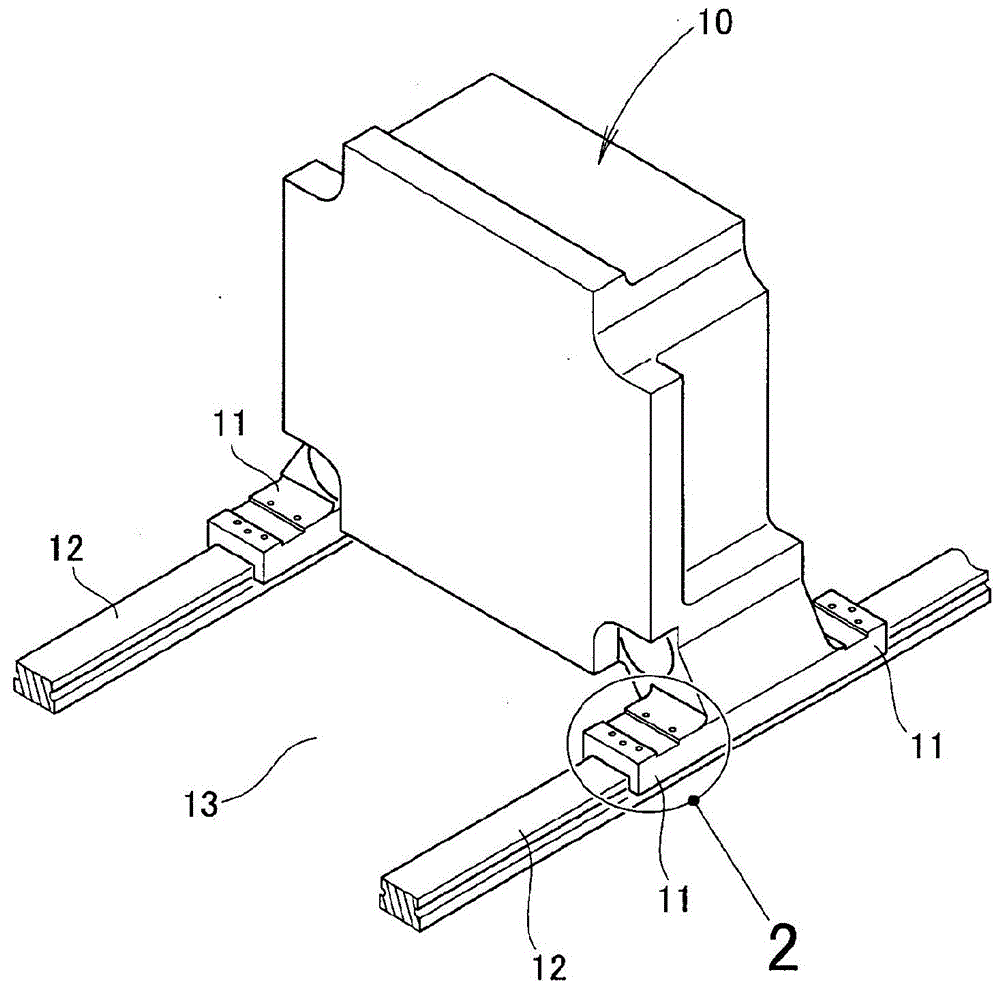
[0033] Such as figure 1 As shown, the movable panel 10 has a total of four leg portions 11 separated from each other in the width direction and in the moving direction at the lower portion. Among them, the two legs 11 , 11 are placed on the left rail 12 , and the remaining two legs 11 , 11 are placed on the right rail 12 . The left and right rails 12 , 12 are placed on a base 13 .

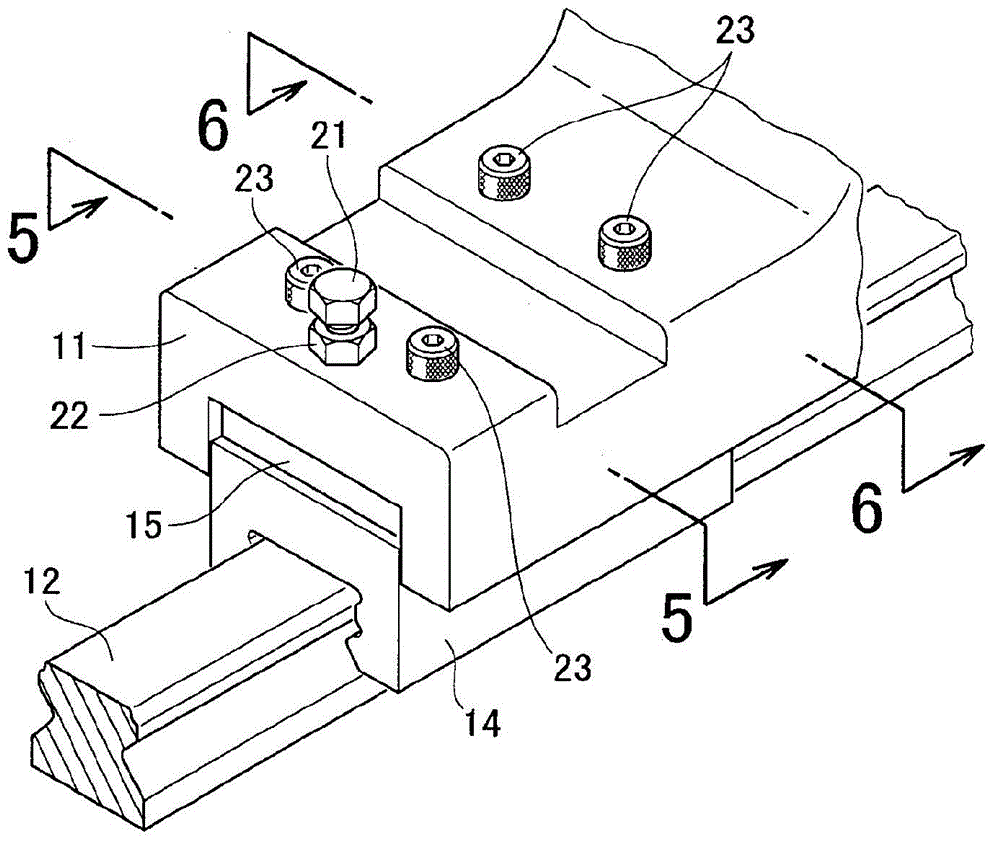
[0034] Such as figure 2 As shown, a slider 14 is fitted into the rail 12 , a flat plate 15 is placed on the slider 14 , and the leg portion 11 is placed on the flat plate 15 .

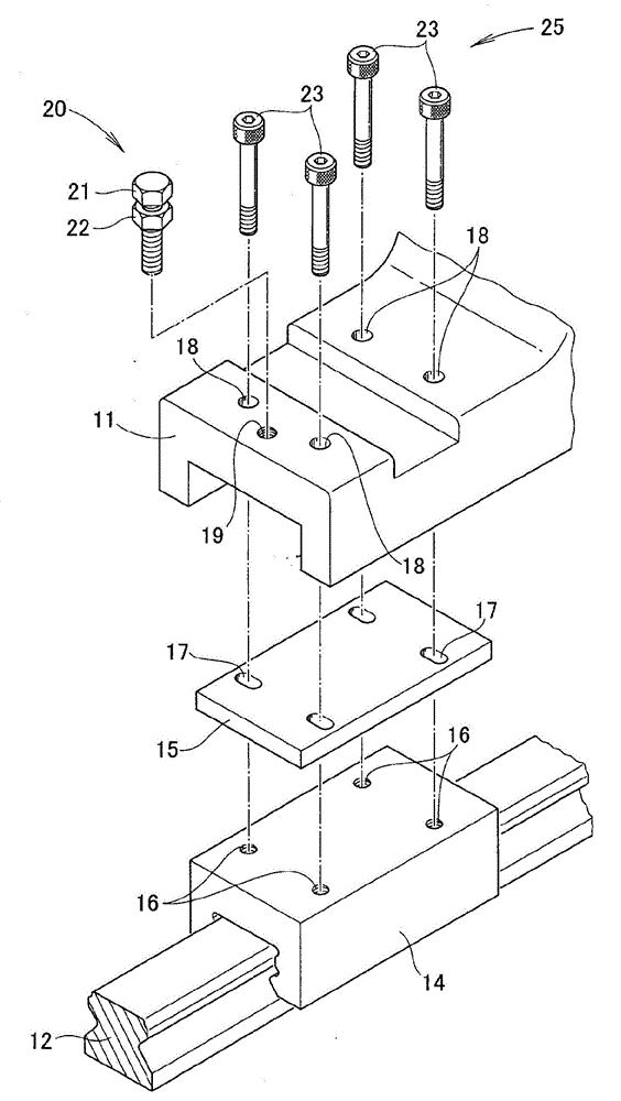
[0035] Such as image 3 As shown, the slider 14 has four internal thread parts 16 on the upper part. The four positions coincide with the vertices of the rectangle.

[0036] The plate 15 has four long holes 17 extending in the width direction (the direction perpendicular to the longitudinal direction of the rail 12).

[0037] The leg portion 11 has four bolt holes 18 and one internally threaded portion 19 arranged at ...


PUM

PropertyMeasurementUnit
thermal conductivityaaaaaaaaaa

Abstract

The invention provides a movable plate with a compact height adjustment mechanism. When a linear guide mechanism (27) is provided with leg sections (11) of the movable plate, a slider (14) and the leg sections (11) of the linear guide mechanism (27) are connected through a height adjustment mechanism (20) and a fastening mechanism (25). The fastening mechanism (25) comprises fastening bolts (23). The height adjustment mechanism (20) is formed by a flat plate (15) and adjusting bolts (21). The adjusting bolts (21) are arranged in the longitudinal direction and are screwed from the upper side. The height adjustment mechanism is limited within the width scope of the leg sections and does not stretch out from the side of the leg sections. Consequently, the height adjustment mechanism is compact.

Description

technical field [0001] The present invention relates to a movable plate of an injection molding device mounted on a base so as to be able to move horizontally via a linear guide mechanism. Background technique [0002] In the injection molding device, the mold is clamped by the fixed plate and the movable plate of the mold clamping mechanism. The resin material is injected into the closed mold by the injection machine. After the resin material is solidified, the movable plate is moved and the mold is opened, thereby taking out the resin product. The movable plate reciprocates along the track on the base. In anticipation of the smoothness of this movement, a linear guide mechanism called a linear guide has been adopted in recent years (for example, refer to Patent Document 1 ( figure 2 )). [0003] As in Patent Document 1 figure 2 As shown, the linear guide block (5) of the linear guide rail (11) (numbers in parentheses indicate the symbols described in Patent Document 1...

Claims


Application Information

Patent Timeline
Patent Type & Authority Applications(China)
IPC IPC(8): B29C45/17
CPCB29C45/1761B29C45/1744B29C45/661B30B15/007
Inventor 西泽龙彦村田敦盐入公彰山口勇
Owner NISSEI PLASTIC IND CO LTD
Learn More