
Optical fiber base material manufacturing method

A manufacturing method and technology of optical fiber base material, which can be applied to manufacturing tools, glass manufacturing equipment, glass deposition furnaces, etc., and can solve problems such as the increase of non-product parts.

Active Publication Date: 2016-02-10
SHIN ETSU CHEM CO LTD
View PDF6 Cites 0 Cited by
  • Summary
  • Abstract
  • Description
  • Claims
  • Application Information

AI Technical Summary

Problems solved by technology

[0010] In addition, in Patent Document 3, a method of changing the moving range of the reciprocating movement is proposed for each moving axis, but in this method, there is a problem of increasing the tapered non-product portions at both ends.

Method used


Image

  • Optical fiber base material manufacturing method
  • Optical fiber base material manufacturing method
  • Optical fiber base material manufacturing method

Examples


Embodiment 1

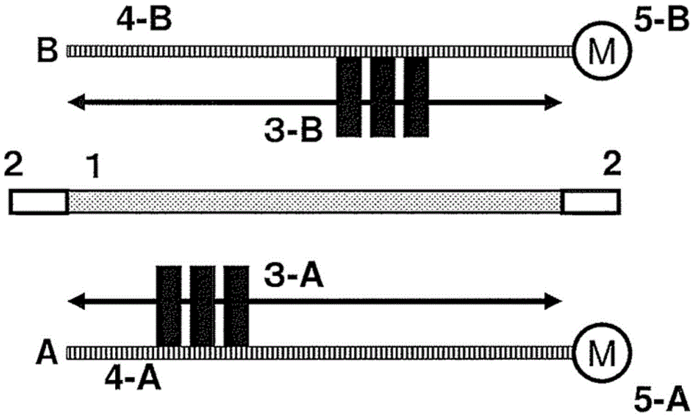
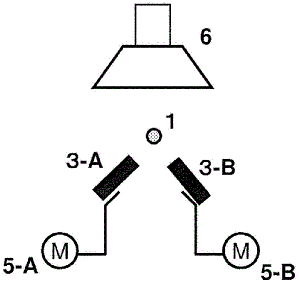
[0046] use as figure 1 , figure 2In the shown apparatus, a porous glass base material for an optical fiber is produced by an external vapor deposition method. As the starting part, dummy rods with an outer diameter of 50 mm and a length of 500 mm were welded to both ends of a mandrel with an outer diameter of 50 mm and a length of 3000 mm, and glass frit was deposited until the outer diameter reached 300 mm.

[0047] The burner uses a multi-nozzle type accumulation burner with a small-diameter combustion-supporting gas nozzle enclosed in a combustible gas outlet, and three burners are arranged at intervals of 150mm on both the A-axis and the B-axis.

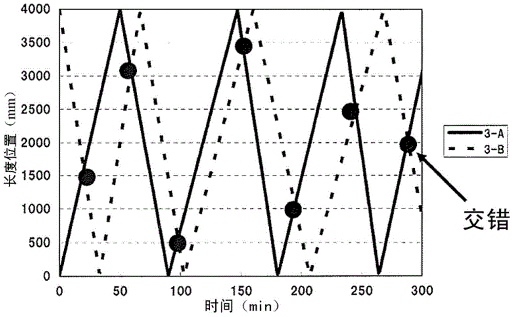
[0048] Such as image 3 As shown, in order not to make the staggered positions of the burners on the A-axis and the B-axis overlap in the length direction of the starting part, as Figure 4 Set the movement speed of the A axis as shown, such as Figure 5 The movement speed of the B-axis was set as shown, and stacking was per...


PUM


Abstract

Provided is an optical fiber base material manufacturing method which manufactures optical fiber base materials at high speed and can still obtain optical fiber base materials with the even stack thickness in the length direction even if multiple burner movement axes are configured. The method includes, while rotating a starting member formed by fusing both ends of a core rod to dummy rods on an axis of the starting member, moving the starting member and burners back and forth relative to each other and depositing glass microparticles on a surface of the starting member. This method also includes setting two or more axes as back and forth movement axes allowing for back and forth movement relative to the starting member; providing a burner facing the starting member on each of the axes; causing each burner to traverse the starting member to an end of the starting member; and changing a position where at least two burners pass by each other during the traversing movement, in a longitudinal direction of the starting member.

Description

technical field [0001] The present invention relates to a method for manufacturing an optical fiber preform capable of high speed and having a uniform thickness in the length direction of a starting part. Background technique [0002] Conventionally, various methods have been proposed for producing an optical fiber preform. In these methods, while rotating the starting member having dummy rods (Damilod) welded to both ends of the mandrel around the axis, the starting member and a plurality of burners are relatively reciprocated, and the surface of the starting member is The external vapor deposition method (OVD method) that accumulates glass particles, dehydrates and sinters them in an electric furnace to obtain an optical fiber base material, can obtain a relatively arbitrary refractive index distribution, and can mass-produce a large-diameter optical fiber base material, so being widely used. [0003] In this external vapor deposition method, studies have been made to in...

Claims


Application Information

Patent Timeline
Patent Type & Authority Applications(China)
IPC IPC(8): C03B37/018
CPCC03B37/0142C03B2207/52C03B2207/64C03B2207/66C03B2207/70Y02P40/57
Inventor 吉田真
Owner SHIN ETSU CHEM CO LTD
Learn More