Decelerating clutch and washing machine

A deceleration clutch and deceleration device technology, which is applied in the field of washing machines, can solve the problems of waste of bottom space, etc., and achieve the effect of increasing washing capacity, reducing volume and remarkable effect

Active Publication Date: 2016-02-10
QINGDAO HAIER WASHING MASCH CO LTD
View PDF2 Cites 5 Cited by
  • Summary
  • Abstract
  • Description
  • Claims
  • Application Information

AI Technical Summary

Problems solved by technology

[0005] Since the deceleration clutch used in the existing washing machine is installed at the bottom of the outer tub / tube, and the diameter of the outer tub / tube is much larger than the diameter of the deceleration clutch, there will be a lot of space around the deceleration clutch, and this part of the space will not be installed. Other structures cause a waste of space at the bottom; and the motor, deceleration device and clutch device of the deceleration clutch are arranged in sequence along the axial direction, resulting in a waste of space at the bottom

Method used


Image

  • Decelerating clutch and washing machine
  • Decelerating clutch and washing machine
  • Decelerating clutch and washing machine

Examples


Embodiment 1

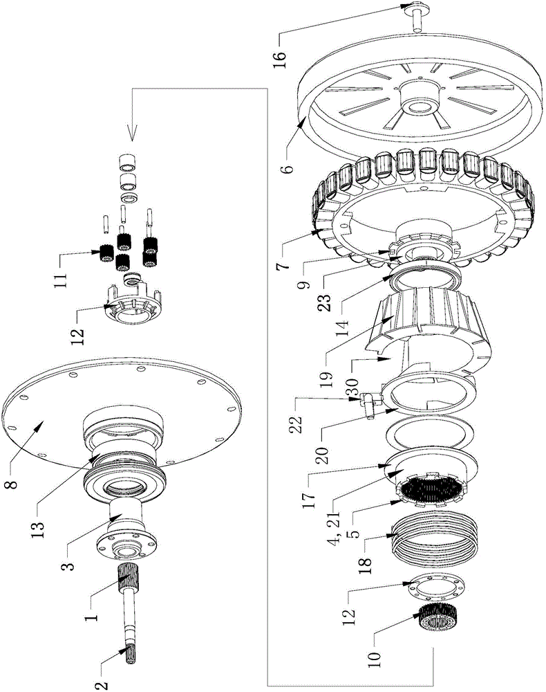
[0048] In this embodiment, the clutch device is at least partly arranged on the periphery of the reduction device, so that the projections of the clutch device and the reduction device on the axis of the reduction clutch at least partially coincide.

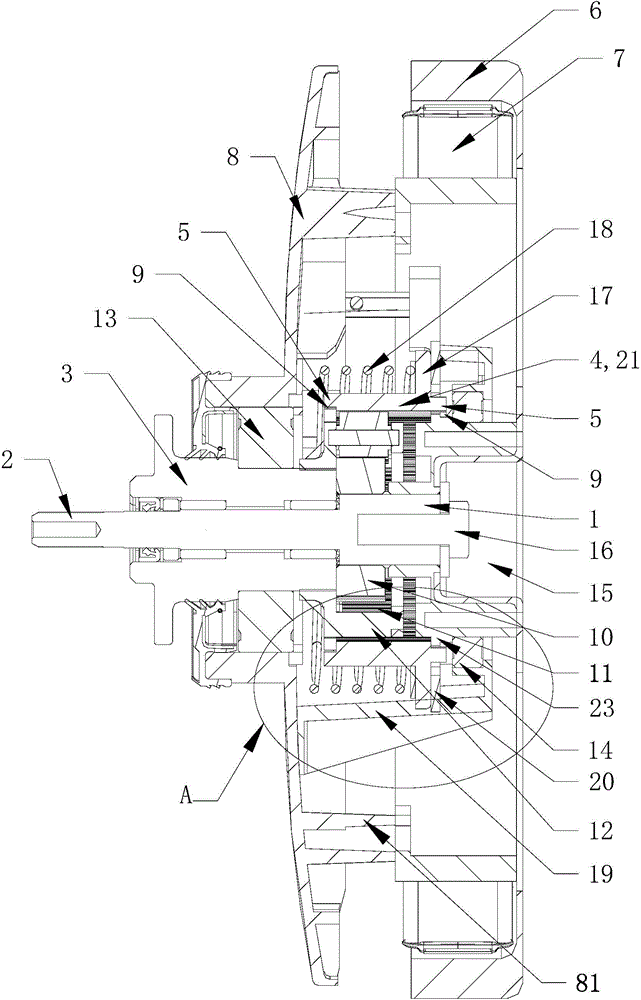
[0049] In this embodiment, the clutch device includes a clutch sleeve 21 that can move axially and a clutch driving device that drives the clutch sleeve 21 to move axially. The clutch shaft sleeve 21 slides up and down driven by the clutch drive device, and the output shaft 2 and the output shaft sleeve 3 switch between different output states.

[0050] In this embodiment, the clutch sleeve 21 is fitted on the outer periphery of the reduction gear, so that the projection of the clutch sleeve 21 and the reduction gear on the axis of the reduction clutch at least partially coincides. Through the above setting, the height space of the original clutch sleeve 21 is saved, and the overall height of the deceleration clutch is reduced, s...

Embodiment 2

[0052] In this embodiment, the reduction device includes a reduction gear train and an inner ring gear engaged with the reduction gear train; the reduction gear train and / or the inner ring gear are at least partially disposed in the hollow portion of the motor. One end of the input shaft is connected with the rotor of the motor, and the other end is respectively connected with the output shaft sleeve and the output shaft through the reduction gear train.

[0053] The different output states of the reduction clutch are determined by the structure of the reduction gear train inside the reduction gear, and the present invention only introduces one of the reduction gear trains; 10 revolving planetary gear 11, and the ring gear 4 meshing with the planetary gear 11; the planetary gear 11 is meshed with the center gear 10 and the ring gear 4 respectively, so that the planetary gear 11 produces a revolution around the axis of the center gear 10; the planetary gear 11 And / or the center...

Embodiment 3

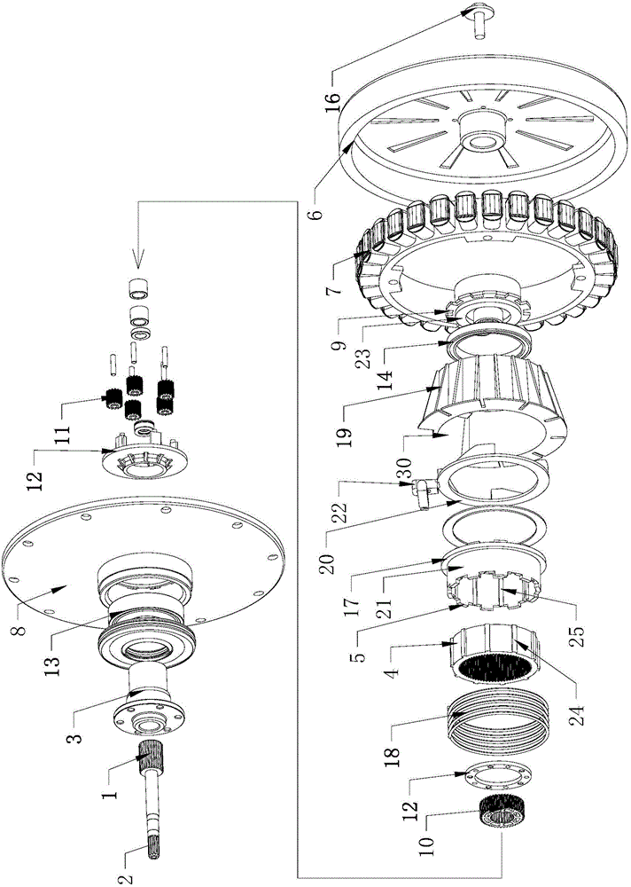
[0059] In this embodiment, the inner wall of the clutch bushing 21 is provided with meshing teeth that mesh with the planetary gear 11, so that the clutch bushing 21 constitutes the ring gear 4 of the reduction gear. The clutch sleeve 21 can be engaged with the planetary gear 11 and can also slide relative to the planetary gear 11 along the axis. Under the action of the clutch driving device, the clutch sleeve 21 is moved in the axial direction to control the output shaft 2 and the output sleeve 3 to switch between different output states.

[0060] In this embodiment, when the clutch sleeve 21 slides in the axial direction, it is necessary to keep the clutch sleeve 21 meshed with at least part of the planetary gears 11 in the reduction gear. Preferably, the clutch sleeve 21 is composed of a straight tube sleeve, and the inner wall of the straight tube sleeve is evenly distributed with meshing teeth meshing with the planetary gear 11 . The meshing teeth extend from one end of ...


PUM


Abstract

The invention relates to a decelerating clutch of a washing machine and the washing machine. The decelerating clutch comprises an input shaft, a decelerating device, a clutch device, an output shaft, an output shaft sleeve and a motor, wherein the clutch device comprises a clutch shaft sleeve which can slide up and down, and end face teeth which are engaged with a fixed device or a motor rotor are respectively formed on the upper and lower ends of the clutch shaft sleeve; at least a part of the decelerating device and/or the clutch device is installed in the hollow part of the motor, so that at least a part of projection of the decelerating device and/or the clutch device coincides with that of the motor on the axis of the decelerating clutch. According to the decelerating clutch and the washing machine, the end face teeth which are engaged with the fixed device or the motor rotor are respectively formed on the upper and lower ends of the clutch shaft sleeve, so that the clutch shaft sleeve is controlled to slide, the output shaft sleeve and the output shaft rotate at the same speed or at differential speed, and the washing machine is controlled to be switched between a dehydration state or a washing state by the decelerating clutch.

Description

technical field [0001] The invention relates to the field of washing machines, in particular to a deceleration clutch of the washing machine, and also to a washing machine equipped with the above deceleration clutch. Background technique [0002] Washing machine is household electrical appliance commonly used in people's daily life, and installation laundry method is different, is divided into drum washing machine and drum washing machine. A drum washing machine generally includes an outer tub, a drum and a motor, and the motor drives the drum to rotate in the outer tub to wash or dehydrate the clothes. Present drum washing machines simply utilize the rotation of the drum for washing, and only use the lifting ribs in the drum to lift and drop the laundry to beat the clothes for washing, so it is difficult to obtain excellent washing effect. The current drum washing machine also has a pulsator in the drum, and the pulsator and the drum are respectively driven by independent ...

Claims


Application Information

Patent Timeline
Patent Type & Authority Applications(China)
IPC IPC(8): D06F37/40
Inventor 迟宗锐栾厚利李作强李全德杜会防徐超
Owner QINGDAO HAIER WASHING MASCH CO LTD
Why Eureka
Try Eureka