
Sucker

A suction cup and disc-shaped technology, applied in the field of suction cup structure, can solve problems such as loss of suction force, and achieve the effect of increasing load and excellent suction power

Active Publication Date: 2016-02-10
GISON MASCH CO LTD
View PDF8 Cites 17 Cited by
  • Summary
  • Abstract
  • Description
  • Claims
  • Application Information

AI Technical Summary

Problems solved by technology

[0003] The suction cup used in the current technology, no matter what kind of structure, can only be used on a smooth surface, such as glass; if it is not used on a smooth surface, the air chamber inside the suction cup will communicate with the outside world and lose its suction force

Method used


Image

  • Sucker
  • Sucker
  • Sucker

Examples


Embodiment Construction

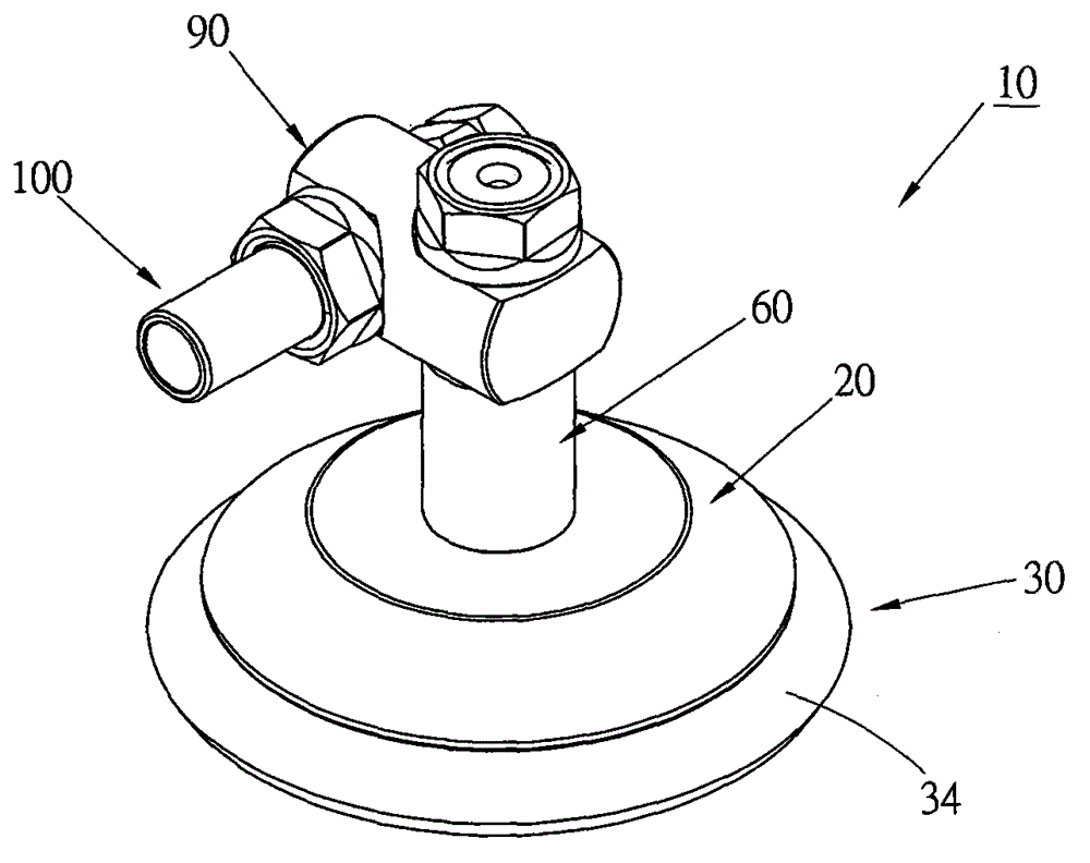
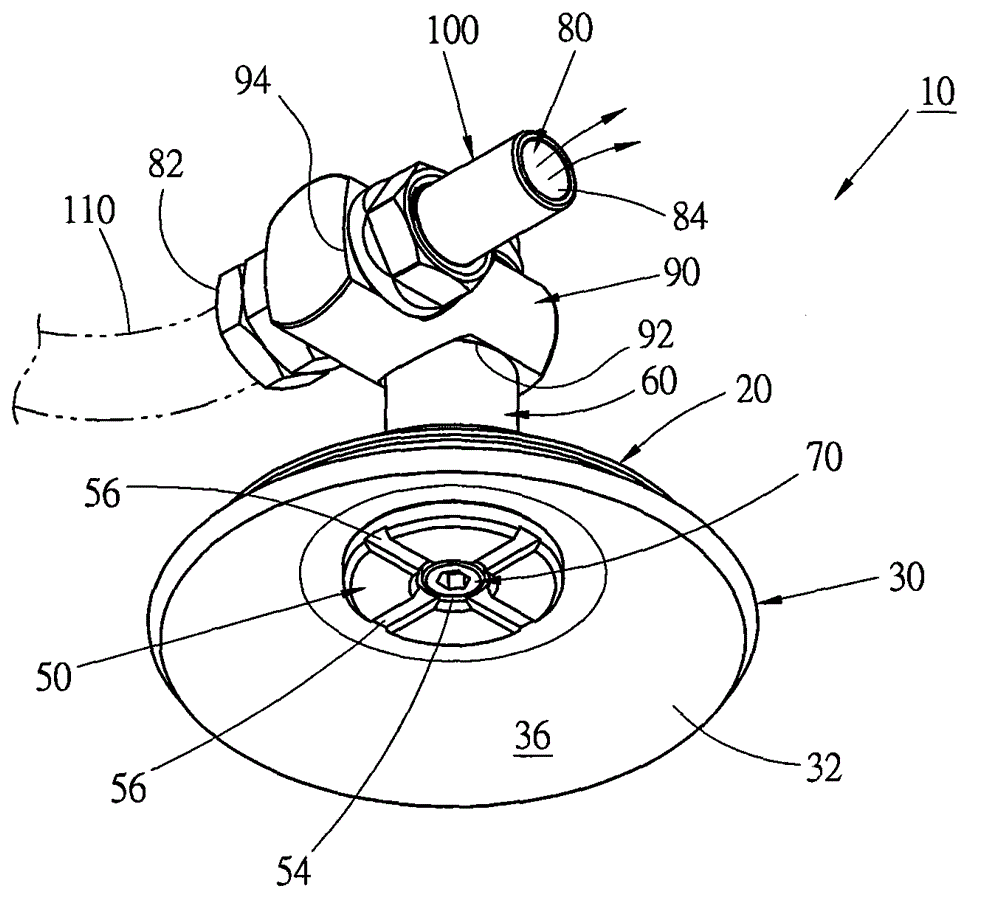
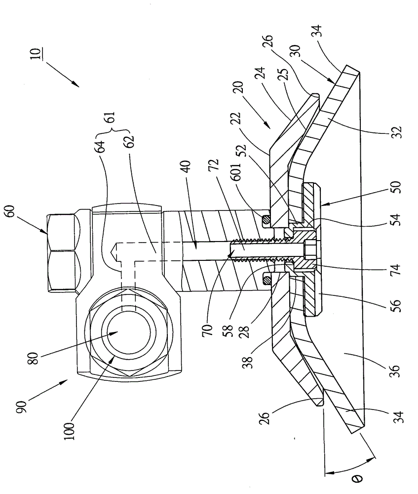
[0026] see Figure 1 to Figure 3 , The suction cup 10 provided by the first preferred embodiment of the present invention mainly includes: a main body 20 , a soft disk body 30 and an air suction channel 40 .

[0027] The body 20 is disc-shaped and made of hard material. It has a flat inner disc portion 22 and an outer disc portion 24 connected to the outer periphery of the inner disc portion 22. The bottom surface of the outer disc portion forms a downward and outwardly inclined The conical surface makes the bottom surface of the main body form a concave conical or conical chamber 25. The bottom surface of the main body 20 is further provided with an annular contact surface 26 connected to the periphery of the container chamber 25 . Preferably, the annular abutment surface 26 is a plane; making the abutment surface an inclined surface can also be an implementation choice. The abutting surface 26 of this embodiment is a horizontal plane.

[0028] The disc body 30 is a disc-s...


PUM


Abstract

A sucker includes: a main body having a bottom face formed with an annular abutment; a disc body made of a flexible material having a tapered annular wall, the disc body being disposed under the bottom face of the main body, an outer circumference of the annular wall being formed with a freely flexible lip edge positioned below the annular abutment face; an air chamber being formed in the disc body; and an air-sucking passage having a first end in communication with the air chamber of the disc body and a second end passing through the disc body and the main body to communicate with outer side. Due to the flexibility of the lip edge, when the sucker sucks a surface of an object, the top face of the lip edge is in contact with the abutment face and supported thereby, and the bottom face of the lip edge is in contact with the surface of the object.

Description

technical field [0001] The present invention relates to a device for generating suction, in detail, it refers to a suction cup structure. Background technique [0002] A suction cup is a device that uses suction to hold and fix items. Suction cups can be roughly divided into two types, one is: a suction cup connected to a power source (such as a suction device), and the other is a suction cup that is not connected to a power source. The principle of the suction cup is to make the air pressure inside the suction cup less than the atmospheric pressure, so as to generate the suction force. [0003] The suction cups used in the current technology can only be used on a smooth surface, such as glass, no matter what kind of structure; if it is not used on a smooth surface, the air chamber inside the suction cup will communicate with the outside and lose its suction force. How to maintain the suction force of the suction cup, and even increase the load that the suction cup can bea...

Claims


Application Information

Patent Timeline
IPC IPC(8): F16B47/00
CPCB25B11/007B25J15/0625B25J15/0683B65G47/91B66C1/0212B66C1/0243B66C1/0256B66C1/02
Inventor 李光台
Owner GISON MASCH CO LTD
Learn More