Ultrasonic self-cleaning anti-scaling ball valve

An ultrasonic and self-cleaning technology, applied to the valve details, valve device, valve shell structure, etc., can solve the problems of sealing failure, affecting the service life of the valve, and easy scaling on the inner wall of the valve cavity, so as to prevent dust accumulation and collision damage Effect

Inactive Publication Date: 2016-02-10
温州欧拉姆品牌运营管理中心(有限合伙)
View PDF7 Cites 3 Cited by
  • Summary
  • Abstract
  • Description
  • Claims
  • Application Information

AI Technical Summary

Problems solved by technology

[0003] After the existing ball valve is used for a long time, the inner wall of the valve cavity is prone to fouling, which

Method used


Image

  • Ultrasonic self-cleaning anti-scaling ball valve
  • Ultrasonic self-cleaning anti-scaling ball valve
  • Ultrasonic self-cleaning anti-scaling ball valve

Examples


Embodiment Construction

[0018] The following specific descriptions of the present invention are given by the examples, which are only used to further illustrate the present invention, and should not be construed as limiting the protection scope of the present invention.

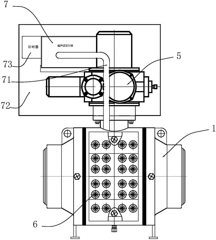
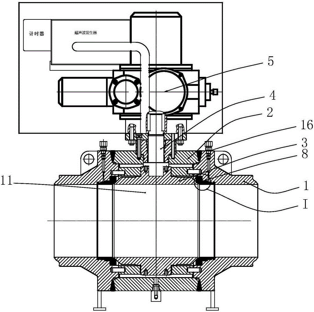
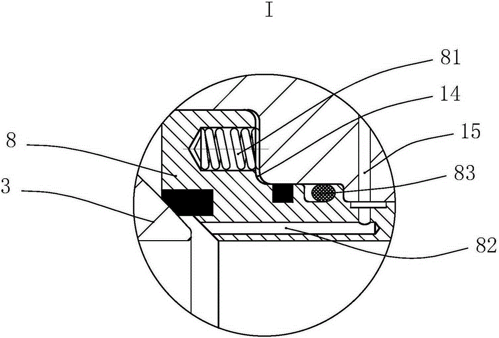
[0019] Such as Figure 1-4 The specific embodiment of the present invention shown is an ultrasonic self-cleaning anti-fouling ball valve, including a valve body 1, a valve cover 2, a ball 3, a valve seat 8, a valve stem 4, and a valve stem driving mechanism 5. On the valve body 1 A valve body flow channel and a valve cavity 11 located on the valve body flow channel are provided, the ball 3 is rotatably set in the valve cavity 11 , the valve stem 4 is rotatably set on the valve body 1 , and the inner end of the valve stem 4 extends into the valve cavity 11 And it cooperates with the sphere 3 in linkage, and the outer end of the valve stem 4 is coordinated with the valve stem driving mechanism 5. The valve stem driving mechanism 5 des...


PUM


Abstract

The invention discloses an ultrasonic self-cleaning anti-scaling ball valve. The ball valve comprises a valve body, a valve deck, a ball body, a valve rod and a valve rod driving mechanism. The valve body is provided with a valve body flow channel and a valve cavity located on the valve body flow channel. The ball body is rotationally arranged in the valve cavity. The valve rod is rotationally arranged on the valve body. The inner end of the valve rod stretches into the valve cavity and is matched with the ball body in a linked mode. The outer end of the valve rod is matched with the valve rod driving mechanism in a linked mode. A plurality of transducers are arranged on the outer sidewall, corresponding to the position of the valve cavity, of the valve body. The ultrasonic self-cleaning anti-scaling ball valve further comprises an ultrasonic generator. The transducers are connected with the ultrasonic generator through transducer connecting pipes. The ultrasonic self-cleaning anti-scaling ball valve has the advantage of being capable of preventing the valve cavity from scaling, thereby improving the rotation flexibility and airtightness of the ball body.

Description

technical field [0001] The invention relates to a ball valve, in particular to an ultrasonic self-cleaning anti-scaling ball valve. Background technique [0002] The ball valve is a kind of valve widely used at present. The existing ball valve structure generally includes a valve body, a valve cover, a ball and a valve stem, and a valve stem driving mechanism. Cavity, the ball is placed in the valve cavity, the valve stem is rotatably arranged on the valve body, and the inner end of the valve stem extends into the valve cavity and cooperates with the ball, and the outer end of the valve stem cooperates with the valve stem driving mechanism. [0003] After the existing ball valve is used for a long time, scaling is easy to occur on the inner wall of the valve cavity, which directly causes the ball to fail to rotate normally, resulting in sealing failure and affecting the service life of the valve. Contents of the invention [0004] The object of the present invention is to...

Claims


Application Information

Patent Timeline
IPC IPC(8): F16K5/06F16K5/22F16K27/06
CPCF16K5/06F16K5/227F16K27/067
Inventor 金志远汪永发黄时然陈子武金汉聂王焕泽叶挺
Owner 温州欧拉姆品牌运营管理中心(有限合伙)
Why Eureka
Try Eureka