Multi-gas-storehouse refrigerator rotary valve
A technology of refrigerators and rotary valves, applied in refrigerators, refrigeration components, refrigeration and liquefaction, etc., can solve the problems of accumulation of assembly tolerances, rising manufacturing costs, rising costs, etc., and achieve reduced sealing surface, reduced cost, and reduced diameter Effect
- Summary
- Abstract
- Description
- Claims
- Application Information
AI Technical Summary
Problems solved by technology
Method used
Image

Examples
Embodiment 1
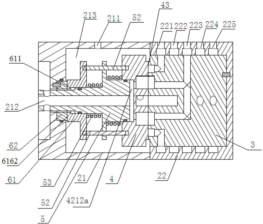
[0043] A rotary valve for multi-gas storage refrigerators, such as Figure 1 ~ Figure 2 As shown, it includes a left valve body 21, a right valve body 22, a stator 3, a mover 4, a valve shaft 5 and a motor 1, the left valve body 21 and the right valve body 22 are sealed and connected to form a valve shell, and the mover 4 and the stator 3 are in common The valve core is formed, the contact surface of the mover 4 and the stator 3 is the valve core sealing surface 43, one end of the valve shaft 5 is connected to the drive of the mover 4, and the other end is connected to the external motor 1; the valve shaft 5 is a hollow structure, and the valve shaft 5 The outer end is a low-pressure gas outlet 212 communicating with a low-pressure gas source, and an air storage valve balance chamber 4212a is formed between the inner end of the valve shaft 5 and the mover 4 .
[0044] The left valve body 21 is provided with a high-pressure gas inlet 211 communicating with a high-pressure gas s...
Embodiment 2
[0054] The difference from Embodiment 1 is that in this embodiment, the structure of the stator 3 is as follows Figure 7 As shown, the structure of mover 4 is as follows Figure 8 As shown in , the interface communicating with the corresponding gas storage is set on the inner ring. At this time, the channel on the side of the regenerator is on the outer ring, and the flow area can be larger.
Embodiment 3
[0056] The stator in this embodiment is as Figure 10 , 11 As shown, the structure of the mover is as Figure 12 , 13 shown.
[0057] Such as Figure 9 As shown, the difference from Embodiment 1 is that the mover 4 is set in the left valve body 21, the stator 3 is set in the right valve body 22, the valve shaft 5 is directly fixedly connected with the mover 4, and the end of the stator 3 is provided with The stator boss 33 forms a low-pressure chamber 2212 and a high-pressure chamber 2211 between the stator boss 33 and the right valve body 22 . The high-pressure chamber 2211 communicates with the high-pressure gas inlet 211 provided on the right valve body 22 and communicates with the stator high-pressure port 3212 at the same time. The low-pressure chamber 2212 communicates with the low-pressure gas outlet 212 opened on the left valve body 21 and communicates with the low-pressure gas source, and communicates with the stator low-pressure port 3211 at the same time.
[0...
PUM
 Abstract
Description
Claims
Application Information
 - R&D
- Intellectual Property
- Life Sciences
- Materials
- Tech Scout
- Unparalleled Data Quality
- Higher Quality Content
- 60% Fewer Hallucinations
Browse by: Latest US Patents, China's latest patents, Technical Efficacy Thesaurus, Application Domain, Technology Topic, Popular Technical Reports.
© 2025 PatSnap. All rights reserved.Legal|Privacy policy|Modern Slavery Act Transparency Statement|Sitemap|About US| Contact US: help@patsnap.com