Tri-mode probe with automatic skew adjustment

A three-mode, probe technology, applied to the parts, instruments, and measuring devices of electrical measuring instruments, can solve expensive and other problems

Inactive Publication Date: 2016-02-10
TEKTRONIX INC
View PDF6 Cites 5 Cited by
  • Summary
  • Abstract
  • Description
  • Claims
  • Application Information

AI Technical Summary

Problems solved by technology

However, this method is quite expensive due to the need to use two channels instead of one

Method used


Image

  • Tri-mode probe with automatic skew adjustment
  • Tri-mode probe with automatic skew adjustment
  • Tri-mode probe with automatic skew adjustment

Examples


Embodiment Construction

[0018] In the drawings, which are not necessarily to scale, like or corresponding elements of the disclosed systems and methods are indicated by like reference numerals.

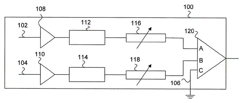
[0019] The disclosed technology involves probes with electronically adjustable delays. Preferably, the probe has electronically adjustable delays in each input path. However, as disclosed in more detail below, some embodiments include an electronically adjustable delay in one input path while the other input has a fixed delay. Probes can be as figure 1 TriMode for a single channel using a test and measurement instrument as shown in TM Probe 100.

[0020] In some embodiments, TriMode TM Probe 100 includes three inputs 102 , 104 and 106 . A first input 102 receives a first signal from the device under test, a second input 104 receives a second signal from the device under test, and a third input 106 is connected to ground. TriMode TM Probe 100 also includes buffers 108 and 110 , cables 112 and 114 , adj...


PUM


Abstract

The invention relates to a tri-mode probe with automatic skew adjustment. A probe, including a first input configured to receive a first input signal, a second input configured to receive a second input signal, a first cable connected to the first input, a second cable connected to the second input, an electronically adjustable delay connected to the first cable, the electronically adjustable delay configured to delay the first input signal to remove a skew between the first input signal and the second input signal, and an amplifier configured to receive the first input signal from the electronically adjustable delay and a second input signal.

Description

[0001] rights and interests [0002] This application claims the benefit of US Provisional Application No. 62 / 030,476, filed July 29, 2014, entitled TRI-MODEPROBEWITHAUTOMATICSKEWADJUSTMENT, which is incorporated herein by reference in its entirety. technical field [0003] The present disclosure relates to probes having electronically adjustable delays in at least one probe input path, and methods for automatically adjusting electronically adjustable delays among different signals to minimize skew and mode switching. Background technique [0004] Differential input probes are commonly used to acquire nominally differential signals (such as on a high-speed serial data bus) from a device under test (DUT) by using a single test and measurement instrument channel. TriMode TM The input probes have the added capability of taking either side of a common mode signal or a differential pair signal as a single-ended signal. [0005] An ideal differential signal consists of two compl...

Claims


Application Information

Patent Timeline
Patent Type & Authority Applications(China)
IPC IPC(8): G01R1/067
CPCG01R1/06766G01R1/06772G01R31/31706G01N29/30G01N29/24
Inventor D.G.克尼林C.R.穆利M.罗克威尔I.G.波洛克
Owner TEKTRONIX INC
Why Eureka
Try Eureka