
A High Gain Adjustable Broadband Corrugated Double Ridge Antenna

A high-gain, corrugated technology, applied in the direction of waveguide horn, radiating element structure, circuit, etc., can flexibly adjust the signal transmission and reception adaptability of double-ridged antennas, affect the flexibility and reliability of double-ridged antennas, and affect double-ridged antennas. Technical development and other issues, to achieve the effect of improving the flexibility of use and signal stability, simple structure, and wide frequency adaptation range

Active Publication Date: 2018-02-16
成都润博科技有限公司
View PDF4 Cites 0 Cited by
  • Summary
  • Abstract
  • Description
  • Claims
  • Application Information

AI Technical Summary

Problems solved by technology

[0002] At present, the double-ridge antenna is widely used in daily life, military communication and other fields, but it is found in actual use that when the current double-ridge antenna is small in size, it often cannot operate according to the frequency of the communication signal. Flexibly adjust the adaptability of the double-ridge antenna signal for sending and receiving, and at the same time, it is easy to cause relatively poor stability of the communication signal. If it is necessary to enhance the signal adaptability of the double-ridge antenna and the sensitivity of adapting to different signals, it is necessary to increase the equipment of the double-ridge antenna structure, which seriously affects the flexibility and reliability of the double-ridge antenna, and seriously affects the development of double-ridge antenna technology. Therefore, in view of this situation, it is urgent to develop a new type of double-ridge antenna to meet the needs of actual use.

Method used


Image

  • A High Gain Adjustable Broadband Corrugated Double Ridge Antenna
  • A High Gain Adjustable Broadband Corrugated Double Ridge Antenna

Examples


Embodiment Construction

[0013] The technical solutions of the present invention will be clearly and completely described below in conjunction with the accompanying drawings of the present invention. Apparently, the described embodiments are only some of the embodiments of the present invention, not all of them. Based on the embodiments of the present invention, all other embodiments obtained by persons of ordinary skill in the art without creative efforts fall within the protection scope of the present invention.

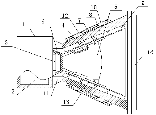
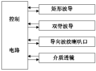
[0014] Such as figure 1 and 2 A high-gain adjustable broadband corrugated double-ridge antenna includes a control base 1, a control circuit 2, a rectangular waveguide 3, a double-ridge waveguide 4, a guiding corrugated horn mouth and a dielectric lens 5, wherein the guiding corrugated horn mouth and the control base The side surface of 1 is connected and distributed coaxially with the control base 1. The rectangular waveguide 3 is installed on the side surface of the control base 1 throug...


PUM


Abstract

The invention relates to a high-gain adjustable broadband corrugated double-ridge antenna, which includes a control base, a control circuit, a rectangular waveguide, a double-ridge waveguide, a guiding corrugated horn mouth and a dielectric lens, wherein the guiding corrugated horn mouth is connected to the side surface of the control base, The rectangular waveguide is installed on the side surface of the control base through the protective cover and embedded in the guiding corrugated bell mouth. There are at least two double-ridge waveguides, which are symmetrically installed on the inner surface of the guiding corrugated bell. At least one dielectric lens is slidably installed through the slide rail. In the guide corrugated bell mouth, the guide corrugated bell mouth includes a positioning substrate, a corrugated reflector, an elastic protective cover and an adjustment mechanism, and the control circuit is embedded in the control base. On the one hand, the present invention can effectively improve the use flexibility and reliability of the double-ridge antenna, and on the other hand, it can automatically perform adaptive adjustment according to the frequency change of the communication signal, thereby effectively improving the use flexibility and signal stability of the double-ridge antenna sex.

Description

technical field [0001] The invention relates to a high-gain adjustable broadband corrugated double-ridge antenna, which belongs to the technical field of antenna equipment. Background technique [0002] At present, the double-ridge antenna is widely used in daily life, military communication and other fields, but it is found in actual use that when the current double-ridge antenna is small in size, it often cannot operate according to the frequency of the communication signal. Flexibly adjust the adaptability of the double-ridge antenna signal for sending and receiving, and at the same time, it is easy to cause relatively poor stability of the communication signal. If it is necessary to enhance the signal adaptability of the double-ridge antenna and the sensitivity of adapting to different signals, it is necessary to increase the equipment of the double-ridge antenna structure, which seriously affects the flexibility and reliability of the double-ridge antenna, and seriously...

Claims


Application Information

Patent Timeline
Patent Type & Authority Patents(China)
IPC IPC(8): H01Q13/02H01Q1/36
Inventor 周明军黄东姚中伟张小兵陈明刘健
Owner 成都润博科技有限公司
Learn More