
Wire harness

A wire harness and main wire technology, applied in the field of wire harnesses, can solve the problems of increasing the cost of components and wire harnesses, reducing the mass production capacity of wire harnesses, etc., to achieve the effect of preventing waste and clear details

Active Publication Date: 2016-02-10
YAZAKI CORP
View PDF7 Cites 23 Cited by
  • Summary
  • Abstract
  • Description
  • Claims
  • Application Information

AI Technical Summary

Problems solved by technology

Therefore, there is a problem that the mass production capacity of the wire harness is lowered, and the cost of the constituent elements and the wire harness is increased

Method used


Image

  • Wire harness
  • Wire harness
  • Wire harness

Examples


Embodiment Construction

[0052] Hereinafter, a first embodiment of the present invention is described with reference to the drawings.

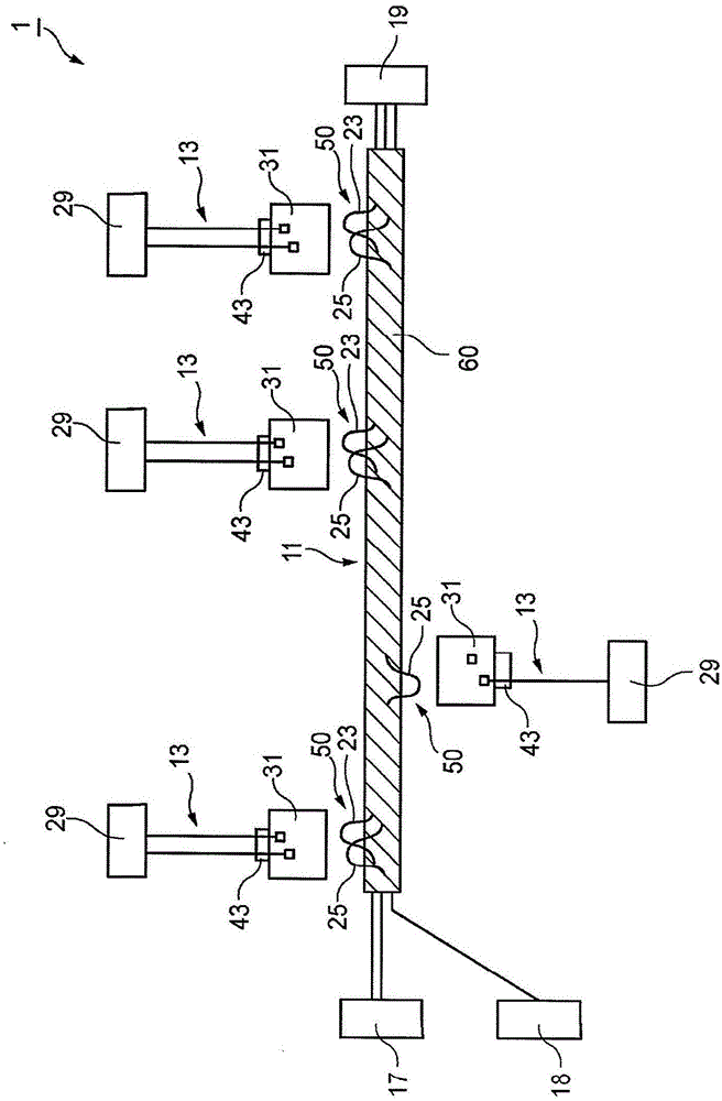
[0053] figure 1 is a schematic diagram of a wire harness according to a first embodiment of the present invention.

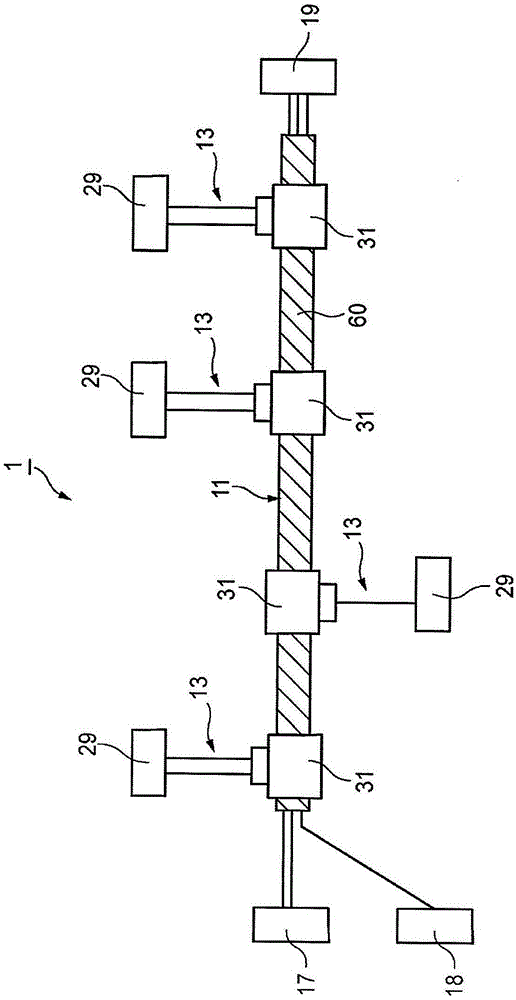
[0054] The wire harness 1 of the first embodiment has a main wire harness 11 to which a first end of an additional connecting member 13 is connected in a branched manner later.

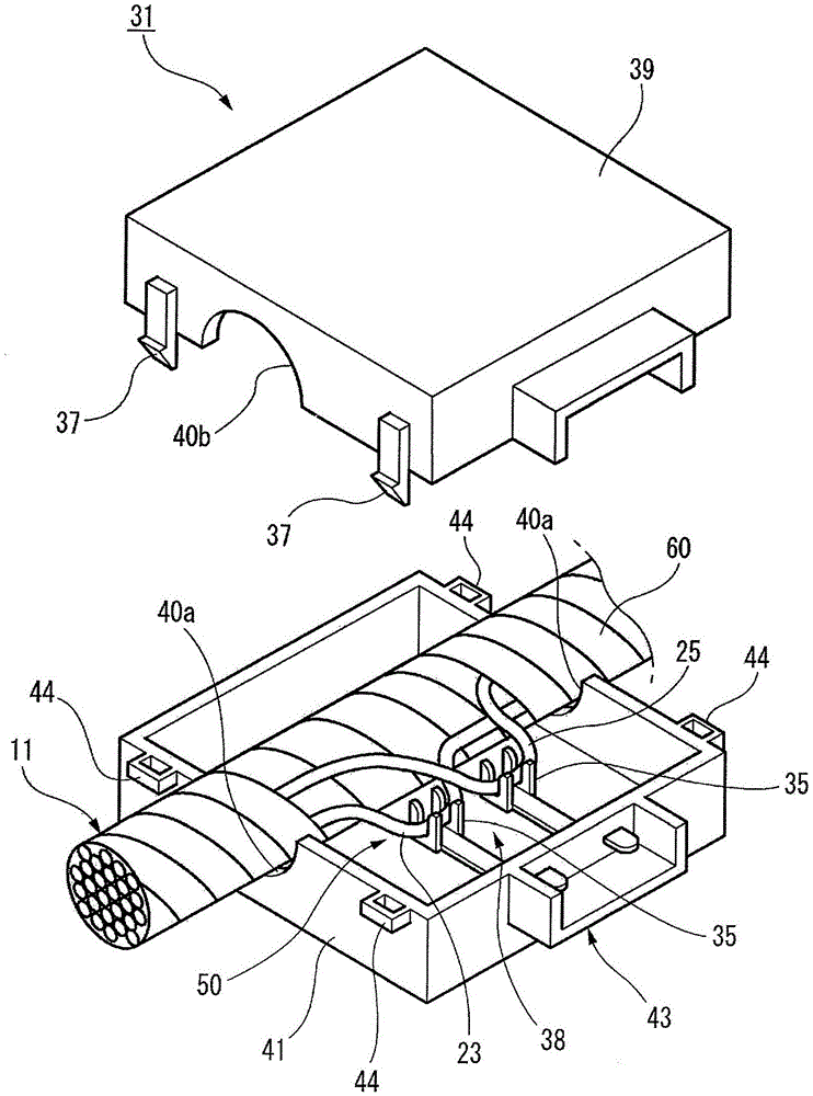
[0055] figure 1 The main wire harness 11 shown is a bundle of four basic types of main wires, including power wires 23, communication wires 25, signal wires, and ground (GND) wires 27, and the main wire harness 11 can be universally installed in multiple installations. in the target vehicle. The main harness 11 is connected to a plurality of electrical devices (for example, a storage battery 17 and a junction box 19 ) and a connector 18 . Such as figure 1 As shown, the insulating tape 60 is wound on the outer circumference of the bundled electric wires of the main wire ...


PUM


Abstract

A wire harness includes a main harness that can be commonly installed in a plurality of installation target vehicles, and a branch connection portion that is visually identifiably provided at a predetermined location on at least any one of a communication wire, a power supply wire, a signal wire, and a ground wire of the main harness. An additional connection member, connected to at least one electrical device that is actually installed in one of the plurality of installation target vehicles, is later connectable to the branch connection portion in a branching manner.

Description

technical field [0001] The present invention relates to a wire harness. Background technique [0002] A large number of various electrical devices, such as lamps, motors, and switching units for operating these lamps and motors, are installed in vehicles. Each of these various electric devices is connected to a wiring harness through which electric power from a storage battery or the like and control signals for controlling the electric device are supplied. A wiring harness consists of multiple wires, connectors, etc. The electric wire includes a core wire and an insulating coating portion covering the core wire. The connector includes a metal terminal mounted at an electric wire end and connected to the electric wire, and a connector housing made of insulating resin and housing the metal terminal. [0003] In recent years, a vehicle network system (for example, refer to JP-A-2004-268630) is used as a communication system that controls a plurality of vehicle electric devi...

Claims


Application Information

Patent Timeline
Patent Type & Authority Applications(China)
IPC IPC(8): H01R11/11
CPCB60R16/0207H01R9/031H01R11/20
Inventor 佐佐木宪明山下寿明
Owner YAZAKI CORP
Learn More