
Braking circuit in alternating current loop

An AC voltage and loop technology, applied in the field of devices that control the drive motor, to achieve the effect of simplifying the control

Inactive Publication Date: 2016-02-10
HEIDELBERGER DRUCKMASCHINEN AG
View PDF9 Cites 0 Cited by
  • Summary
  • Abstract
  • Description
  • Claims
  • Application Information

AI Technical Summary

Problems solved by technology

The disadvantage of such an arrangement of the braking resistor in the DC voltage intermediate circuit is that in the event of failure of the inverter between the DC voltage intermediate circuit and the drive motor, electrical braking is no longer possible because the electrical energy from the drive motor is interrupted through the Inverter output into DC voltage intermediate circuit with braking resistor

Method used


Image

  • Braking circuit in alternating current loop

Examples


Embodiment Construction

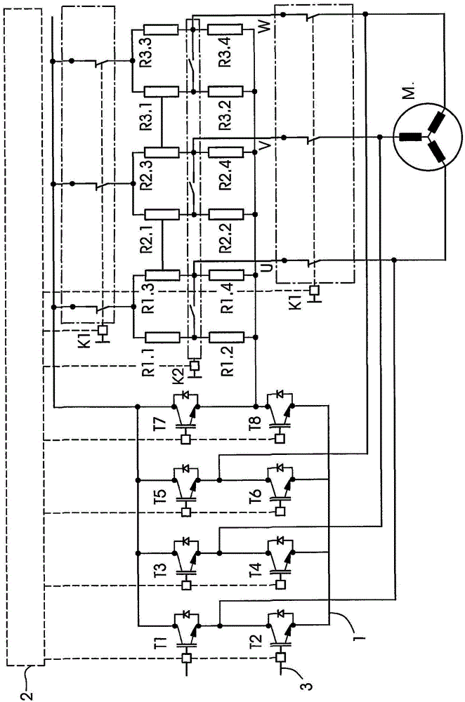
[0017] A device for controlling the drive motor M by means of the control unit 2 is shown in the drawing. Control unit 2 essentially consists of electronic circuit logic for regulating drive motor M and all switches and power semiconductors of the device. The device has an inverter 1 which is connected to a direct voltage intermediate circuit 3 . The inverter 1 can be implemented unidirectionally or bidirectionally. In the first case, the inverter 1 can only convert the DC voltage from the DC intermediate circuit 3 into an AC voltage for controlling the drive motor M. If the inverter 1 is bidirectional, it can also convert the electrical energy from the AC voltage circuit of the drive motor M into a DC voltage and feed it back into the DC intermediate circuit 3 .

[0018] The inverter 1 consists of six transistors T1 to T6 which are controlled by the control unit 2 in such a way that the desired motor voltage for controlling the drive motor M is supplied in the AC voltage ci...


PUM


Abstract

The invention relates to a device used for controlling a drive motor (M). The device comprises a control unit (2) and an inverter (1) connecting the device and a direct current voltage loop (3). Alternating current voltage is supplied to the drive motor (M) via the inverter (1). Power resistors (R1.1 to R3.4) are present in an alternating current voltage loop and between the inverter (1) and the drive motor (M).

Description

technical field [0001] The invention relates to a device for controlling a drive motor having a control unit and an inverter for connecting the device to a direct voltage circuit, wherein the drive motor is supplied with an alternating voltage via the inverter. Background technique [0002] These devices are used today in many electrically driven machines and installations for speed-regulated and / or torque-regulated control of drive motors. In these devices, the alternating current voltage of the common current grid (Stromnetz) is usually first converted into a direct current voltage by means of a rectifier, and then the direct voltage is converted again by means of an inverter into the corresponding desired polyphase for controlling the drive motor AC voltage. In this case, the inverter is controlled by the control unit in order to be able to control the semiconductor components of the inverter differently and thus to vary the AC voltage output to the drive motor. The rot...

Claims


Application Information

Patent Timeline
IPC IPC(8): H02P3/22
CPCH02P3/22
Inventor J·赖特尔K·科拉尔R·维尔豪尔A·舒尔茨
Owner HEIDELBERGER DRUCKMASCHINEN AG
Learn More