Power unit with brake function for unit cascaded high-voltage frequency converter

A power unit, high-voltage frequency conversion technology, applied in output power conversion devices, electrical components, conversion equipment for intermediate conversion to DC conversion, etc. High cost and other problems, to achieve the effect of small loss, simple structure and low cost

Inactive Publication Date: 2010-01-27
SHANXI KEDA AUTOMATION CONTROL
View PDF0 Cites 12 Cited by
  • Summary
  • Abstract
  • Description
  • Claims
  • Application Information

AI Technical Summary

Problems solved by technology

[0003] The structural composition of the power unit series multi-level high-voltage inverter widely used at present: it is mainly composed of multiple complex winding isolation phase-shifting transformers, multiple power units and control systems, in which multiple power units are connected in series to form an adjustable frequency. The high-voltage AC power supply; the circuit that constitutes the power unit of this high-voltage inverter is composed of a diode rectifier bridge, a large-capacity capacitor connected in parallel to the DC bus, a voltage equalizing resistor connected in parallel to these capacitors, and a single-phase bridge inverter circuit. , but this power unit does not have an electrical braking function
[0004] In the industry, if the high-voltage inverter is required to work in two-quadrant or four-quadrant situations, if it cannot realize electrical braking, it cannot meet the applications in these special fields. This special application field requires the inverter to start and stop suddenly with load. If there is no electric braking function, emergency stop cannot be realized. However, there are some frequency converters with self-contained energy feedback function. The frequency converter with feedback function is expensive, and it is not suitable for some occasions where the feedback energy is not large and fast braking and starting are required.

Method used


Image

  • Power unit with brake function for unit cascaded high-voltage frequency converter
  • Power unit with brake function for unit cascaded high-voltage frequency converter
  • Power unit with brake function for unit cascaded high-voltage frequency converter

Examples


Embodiment Construction

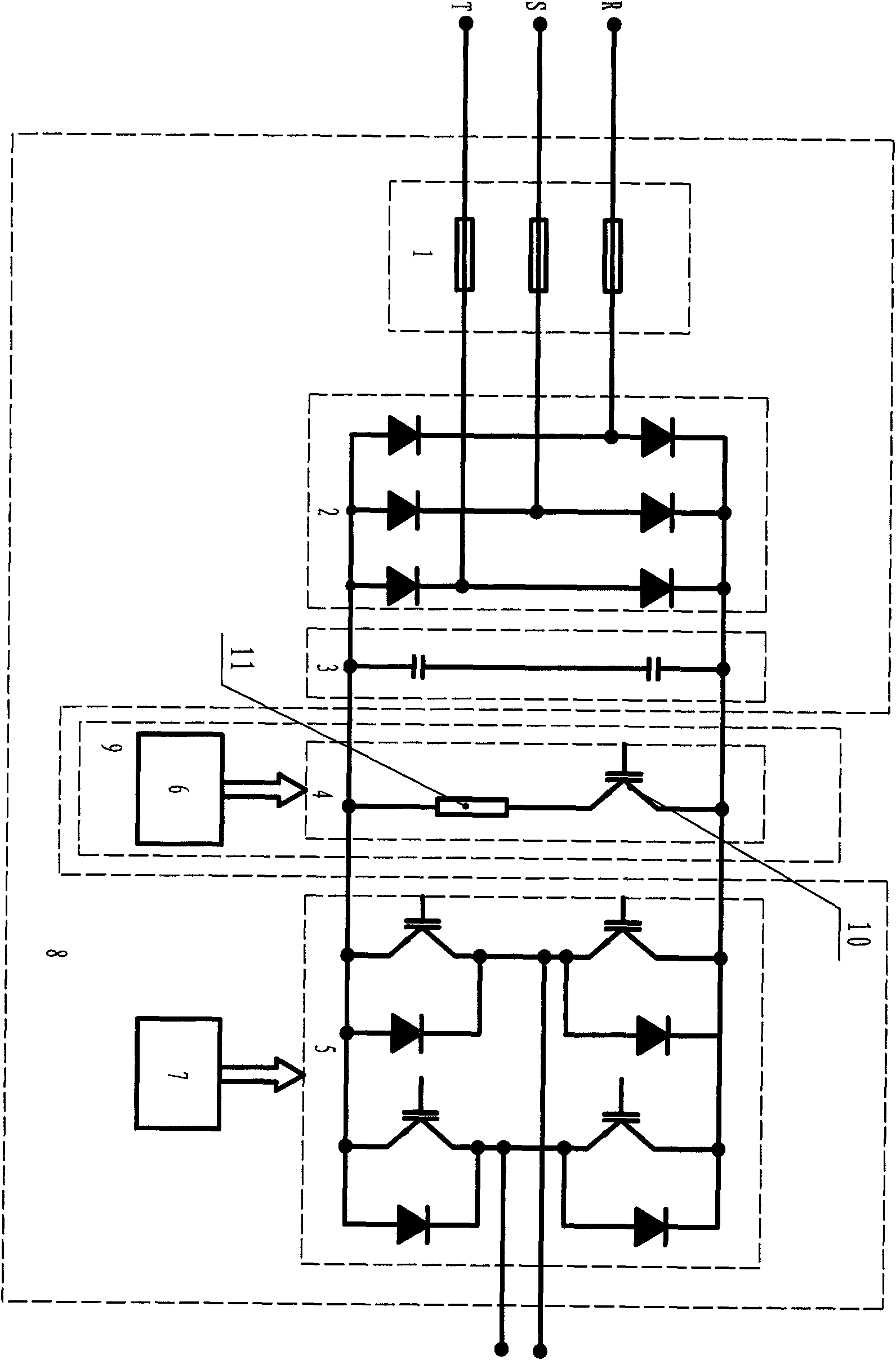
[0027] Such as figure 1 The shown circuit schematic diagram of the present invention is used for the power unit of the unit series high-voltage frequency converter with braking function, and the power unit in the existing series high-voltage frequency converter is replaced by the power unit with braking function of the present invention , which includes a power unit 8 and a braking unit 9, the power unit 8 includes a short-circuit protection circuit 1 composed of sequentially connected three-phase fuses, an uncontrollable bridge rectifier circuit 2, a DC filter circuit 3 composed of capacitors, a single Phase bridge inverter circuit 5 and power unit controller 7, short circuit protection circuit 1 is connected with uncontrollable bridge rectifier circuit 2, uncontrollable bridge rectifier circuit 2, DC filter circuit 3 and single-phase bridge inverter circuit 5 are connected in parallel Together, the single-phase bridge inverter circuit 5 is also connected to the power unit co...


PUM


Abstract

The invention relates to a power unit with brake function for a unit cascaded high-voltage frequency converter, which belongs to the technical field of power electronic equipment. The invention aims at providing the power unit of the cascaded high-voltage frequency converter, which has small feedback energy and can be used under the occasions which require rapid brake and startup. The adopted technical scheme is as follows: the power unit with the brake function for the unit cascaded high-voltage frequency converter comprises the power unit and a brake unit, the power unit comprises a short-circuit protection circuit, a bridge rectifier circuit, a direct current filter circuit, an inverter circuit and a controller of the power unit which are connected in sequence, wherein the short-circuit protection circuit is connected with the rectifier circuit, the rectifier circuit, the direct current filter circuit and the inverter circuit are connected in parallel, the inverter circuit is further connected with a control circuit of the power unit, the brake unit is connected in the power unit in parallel, and the brake unit consists of an energy consumption brake circuit and a brake controller, thereby being widely applied in various types of high-voltage frequency converters.

Description

technical field [0001] The invention is used for a power unit with a braking function of a unit series high-voltage frequency converter, and belongs to the technical field of power electronic equipment. Background technique [0002] The frequency converter is a conversion device that converts power-frequency AC power into frequency-adjustable AC power by using the on and off functions of semiconductor power devices; the device first converts power-frequency AC power into DC power, and then converts the DC power into frequency-adjustable AC power. With the rapid development of microelectronics and power electronics technology, as a product of power electronics technology in the 21st century, high-voltage frequency converters have been widely used in many fields of the national economy and are playing an increasingly important role. [0003] The structural composition of the power unit series multi-level high-voltage inverter widely used at present: it is mainly composed of mu...

Claims


Application Information

Patent Timeline
Patent Type & Authority Applications(China)
IPC IPC(8): H02M5/44H02M1/36
Inventor 付国军李轩青
Owner SHANXI KEDA AUTOMATION CONTROL
Why Eureka
Try Eureka